DVP-ES3 Series Operation Manual
The output mapping areas are D25000-D25999, and the input mapping areas are D24000-D24999, as the
following table shows.
D25000–D25031
SDO request information, NMT service information, and
Emergency request information
64 bytes
D24000–D24031 SDO reply information, and Emergency reply information 64 bytes
If a DVP-ES3 Series functions as a slave, the output mapping areas are D25032–25063, and the input
mapping areas are D24032–24063 as the following table shows.
D25032~25063
10.2 Installation and Network Topology
This section introduces the physical dimensions of DVP-ES3 Series PLC, the HWCONFIG settings, the CAN
interface, the CANopen network framework, and the maximum communication distance.
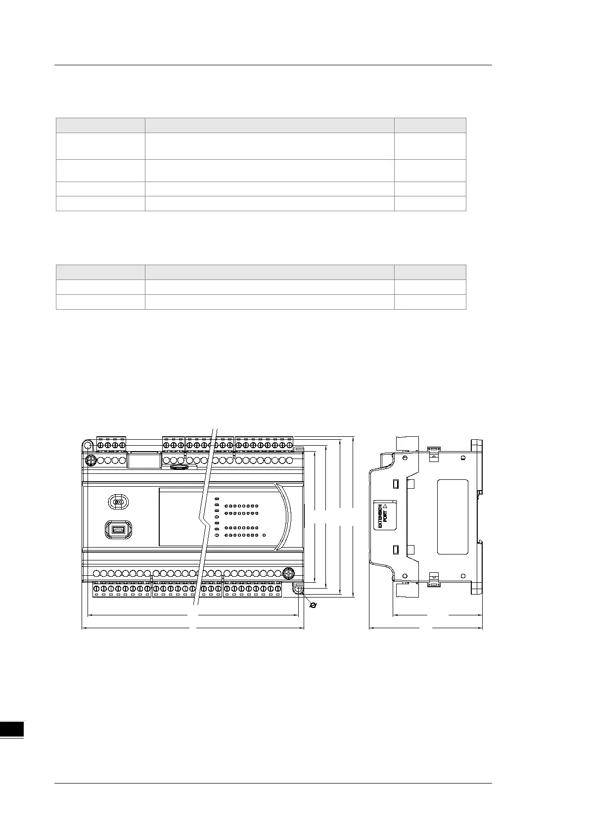
10.2.1 The Dimensions of DVP-ES3 Series PLC
L1
L
90
98
106
110
61.5
78
4.5x2
Unit: mm
 Loading...


