DVP-ES3 Series Operation Manual
5-16
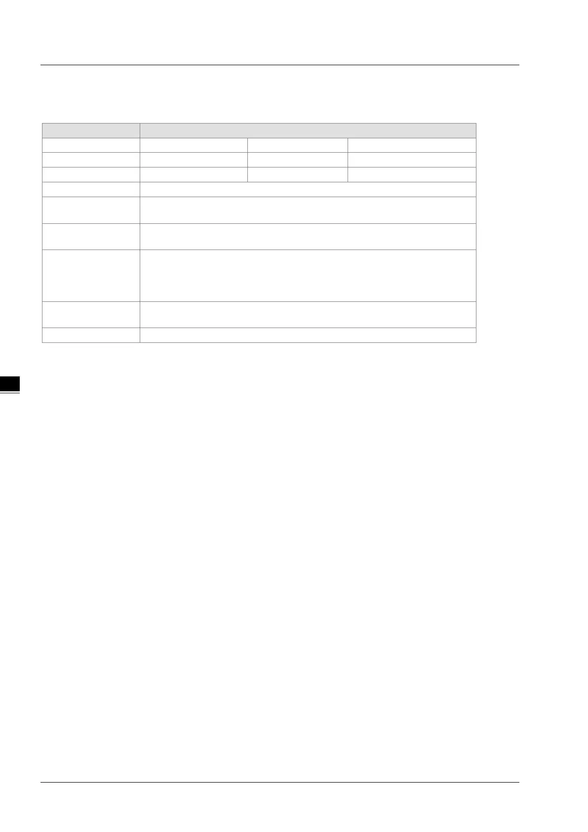
5.2.11 32-bit Counters (HC)
Characteristics of the 32-bit counter
Type Up/down counter Up counter High-speed counter
Number HC0–HC63 HC64–HC199 HC200–HC255
-2,147,483,648 to +2,147,483,647
Specification of the
The counter setting value can be either the constant or th
e value occupying two data
registers (32-bit).
Change of the current
The counter keeps counting even after the value of the counter matches the counter
setting value.
Output contact
The contact is ON when the value of the addition counter matches the counter
setting value.
The contact is reset to OFF when the value of the subtraction counter matches the
Reset
When the RST instruction is executed, the current value is cleared to zero, and the
After the DCNT instruction scan is complete, the contact acts.
32-bit general-purpose addition/subtraction counter
1. The difference between the 32-bit general-purpose addition counters and the 32-bit general-purpose subtraction
counters depends on the states of the special auxiliary relays SM621–SM684. For example, the counter HC0 is
an addition counter when SM621 is OFF, whereas HC0 is a subtraction counter when SM621 is ON.
2. You can use either the constant or the value in the data registers as the counter setting value, and this setting
value can be positive or negative. If you use the value in the data registers as the counter setting value, this
setting value occupies two consecutive registers.
3. For the general-purpose counter, the current value of the counter is cleared when power is lost. If the counter is
latching, the current value of the counter and the state of the contact before loss of power is retained. The latched
counter counts from the current value when power is restored.
4. If the counter counts up from 2,147,483,647, the next incremental value is -2,147,483,648. If the counter counts
down from -2,147,483,648, the next incremental value is 2,147,483,647.