DVC6000f Series
March 2006
6-8
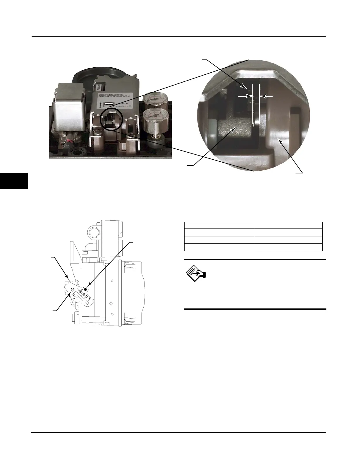
Figure 6-5. Relay Beam, Lower View
0.14 mm
(0.055 INCH)
TRAVEL STOP
RELAY BODY
ADJUSTMENT DISC
W8278
Figure 6-6. Type DVC6010f Digital Valve Controller Showing
Feedback Arm in Position for Travel Sensor Adjustment
Feedback Arm
(key 79)
A
B
Travel
Sensor
Shaft
Alignment Pin
(key 46)
A7023 / IL
6. From the Calibrate menu, select Travel Sensor
Adjust. Follow the prompts on the Field Communicator
display to adjust the travel sensor counts to the value
listed in table 6-1.
Table 6-1. Travel Sensor Counts
Digital Valve Controller Travel Sensor Counts
Type DVC6010f / DVC6015
3375 $ 150 counts
Type DVC6020f / DVC6025
8400 $ 150 counts
Type DVC6030f / DVC6035
3375 $ 150 counts
Note
In the next step, be sure the feedback
arm surface remains flush with the end
of the travel sensor shaft.
7. While observing the travel sensor counts, tighten
the screw that secures the feedback arm to the travel
sensor shaft. Be sure the travel sensor counts remain
within the tolerances listed in table 6-1. Paint the
screw to discourage tampering with the connection.
8. Disconnect the Field Communicator and Fieldbus
power source from the instrument.
9. Remove the alignment pin and store it in the
instrument housing.
10. Install the digital valve controller on the actuator.
DVC6020f and DVC6025 Digital Valve
Controllers
1. Remove supply air and remove the instrument from
the actuator.
6
 Loading...


