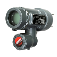
DVC6000f Series
March 2006
10-14
the hole marked “A” on the feedback arm. Fully
engage the alignment pin into the tapped hole in the
housing. Position the feedback arm so that the outer
surface is flush with the end of the travel sensor shaft.
7. Connect a multimeter set to a resistance range of
50,000 ohms. Measure the resistance between pins 1
and 3 of the travel sensor connector. Refer to figure
10-6 for pin location. The resistance should be
between 40,000 and 50,000 ohms.
8. Multiply the result in step 7 by 0.048 to get a
calculated resistance. The calculated resistance
should be in the range of 1920 to 2400 ohms.
9. Re-range the multimeter to a resistance of 3000
ohms between pins 2 and 3 of the travel sensor
connector. Refer to figure 10-6 for pin location.
10. Adjust the travel sensor shaft to obtain the
calculated resistance determined in step 8, $ 100
ohms.
Note
In the next step, be sure the feedback
arm outer surface remains flush with
the end of the travel sensor shaft.
11. While observing the resistance, tighten the screw
(key 80) to secure the feedback arm to the travel
sensor shaft. Be sure the resistance reading remains
at the calculated resistance determined in step 8,
$100 ohms. Paint the screw to discourage tampering
with the connection.
12. Disconnect the multimeter from the travel sensor
connector.
13. For the DVC6030f only, connect the travel sensor
connector to the PWB as described in Replacing the
Module Base.
14. Travel sensor replacement is complete. Install the
digital valve controller on the actuator as described in
the Installation section.
Travel Sensor Adjustment with the Field
Communicator
The next two steps do not apply if you used a
multimeter to adjust the travel sensor. Perform these
steps only if you elected to adjust the travel sensor
using the Field Communicator.
15. For the DVC6030f only, connect the travel sensor
connector to the PWB as described in Replacing the
Module Base.
16. For both the DVC6030f and the DVC6035,
perform the appropriate Travel Sensor Adjust
procedure in the Calibration section.
Stroking the Digital Valve Controller
Output
After completing maintenance procedures, confirm
proper valve operation by stroking the digital valve
controller output. Refer to page 5-39 of the transducer
block section of Detailed Setup / Blocks.
10

 Loading...


