REV.-A
4.2.5 Disassembly of Printer Mechanism
This section details the removal of components
from the printer mechanism. Figure A-1 9 shows an
exploded diagram of the printer mechanism, offering a view of the various components. Table
A-1 7
lists the components by name. COMPONENT NAME LIST.
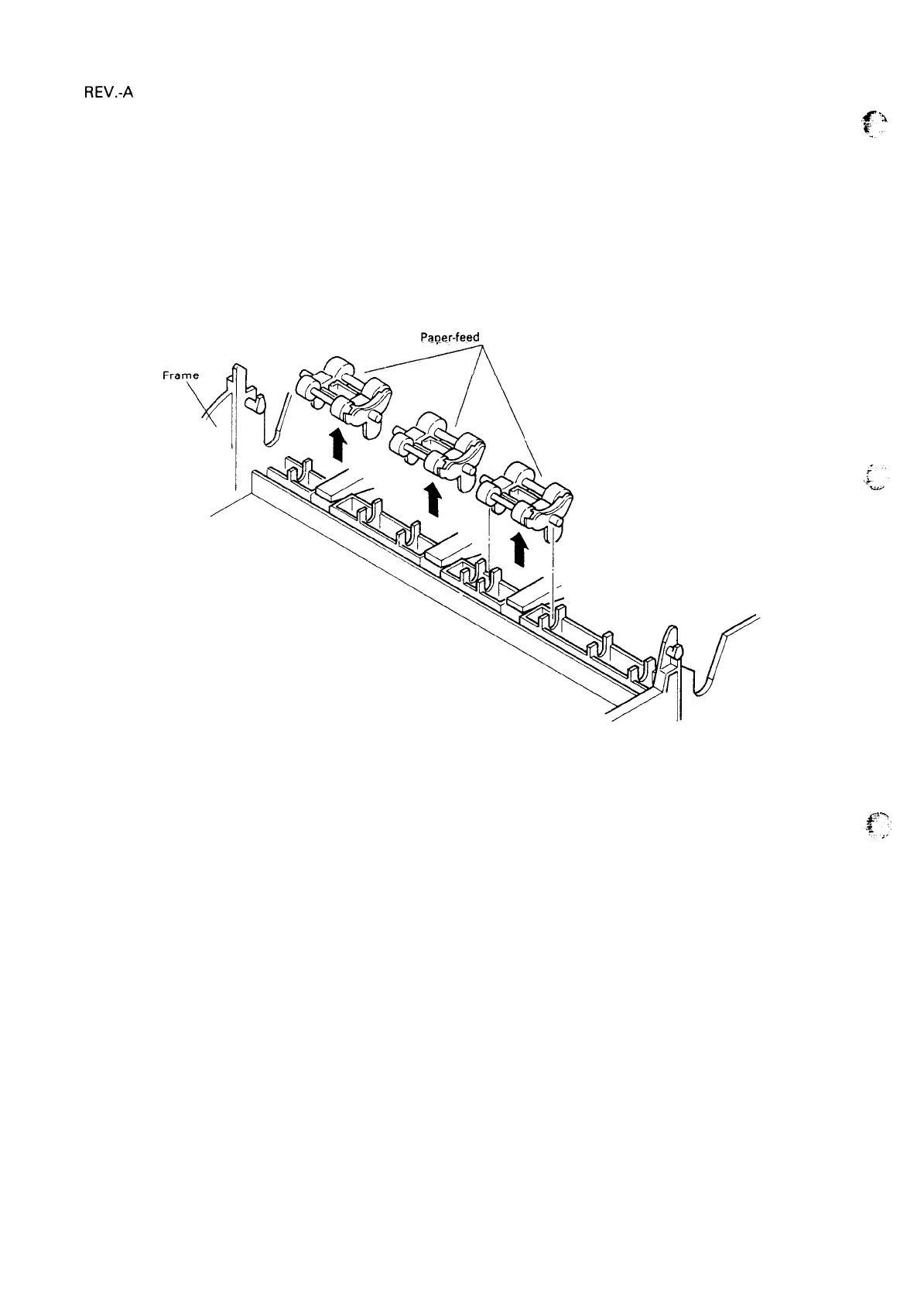
4.2.5.1 Removal of The Paper-Feed Mechanism
1. Remove the printer mechanism (refer to Section 4.2.4).
2. Remove the three paper-feed rollers from the frame.
Paoer-feed
rollers
Figure 4-18. Removal of Paper Feed Rollers
4-14
 Loading...