REV.-A
2.2.3 Carriage Operation
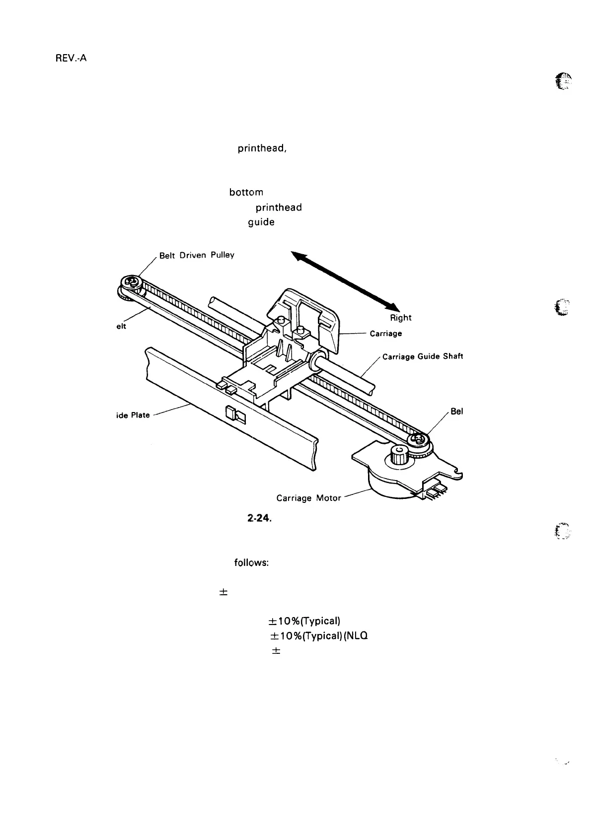
This section describes the carriage operation.
2.2.3.1 Carriage Mechanism
The carriage mechanism includes the
printhead, the carriage, the timing belt, the carriage motor, and
the platen. Figure 2-24 shows the carriage mechanism.
The timing belt is connected to the
bottclm of the carriage. The belt is driven by the carriage motor
and moved via the belt-driven pulley. The
printhead is mounted on the carriage, and the entire unit is
moved right and left along the carriage
guide shaft and plate.
Left
Timing B
Carriage Gu
t
Figure
2!-24.
Carriage Mechanism
step motor
f
,:;>
,.,
.
,..,,
.
L
,,
,,:,,
: Driving Pulley
2.2.3.2 Carriage Motor Specifications
Carriage motor specifications are as
follclws:
Type
4-phase, 48-pole
Drive Voltage
24 V
*
10%
Coil Resistance
11 ohms &7% at 25 degrees C
Current
Driving: 0.36 A
&
IO%(Typical)
(Super Draft or Draft Printing)
0.28 A
&
IO%(Typical)
(NLQ Printing)
Holding: 0.09 A
&
10%
{;,:
2-22
 Loading...