REV.-A
5.1 GENERAL
Troubleshooting is based on the idea that error symptoms vary according to the defective component.
Troubleshooting may involve either unit replacement or unit repair, each of which is treated separately
below.
First try to determine the defective unit by referring to section 5.2. The flowcharts in the section should
help you to isolate the defective unit. Then refer to section 5.3 for instructions for further checking and
for replacement. Section 5.3 lists, for various symptoms, the potentially defective unit(s) that may
account for them. In addition, the section mentions the appropriate waveforms and resistance values
that should be checked for.
If trouble occurs in the printer mechanism, refer to section 5.3.3, which specifies procedures for
identifying defective components, and the replacements, adjustments, and lubrication which should
be carried out.
5.2
UNIT REPLACEMENT
This section correlates symptoms with the potentially defective units that may be causing them. The
unit numbers are listed in Table 5-1.
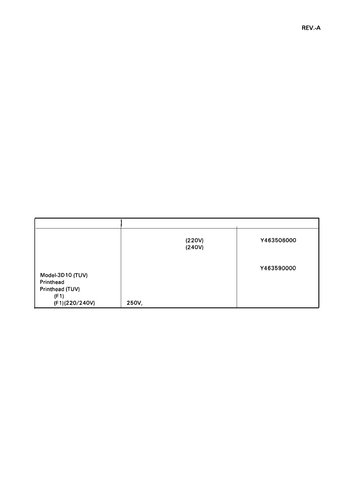
Table 5-1. Unit Replacement Numbers
Name of Unit
I
Description
I
Unit No.
TA Filter Unit
TA Filter Unit
TA Filter Unit
TAMA Board
TAPNL-W
Model-3Dl O
Model-3D10
(TUV)
Printhead
Printhead
(TUV)
Fuse
(Fl)
(120V)
Fuse
(Fl)
(220/240V)
Filter and Transformer (120V)
Filter and Transformer
(220V)
Filter and Transformer
(240V)
Main Board
Control Panel
Printer Mechanism
Printer Mechanism
125V, 1.25A
250V, 0.63A
Y463504000
Y463506000
Y463507000
Y46320 1000
Y46350 1000
Y463590000
Y463590 100
F425 100000
F425200000
X50206 1050
X502063030
5-1
 Loading...