REV.-A
2.2 PRINCIPLES OF OPERATION
This section describes the operation of each component.
2.2.1 Power Supply Circuit
The electrical power required by this mechanism is developed using the TA
Filter Unit (which combines
a filter and a power transformer) and the
TAMA board. The AC input passes first through the filter circuit,
where line noise is removed, and is then set to the transformer, where it is stepped down into two
separate voltages: AC 26V and AC 12V.
“The
transformer output is sent to the power circuits on the
TAMA
board, which converts the power to the DC voltages (see below) required for operation.
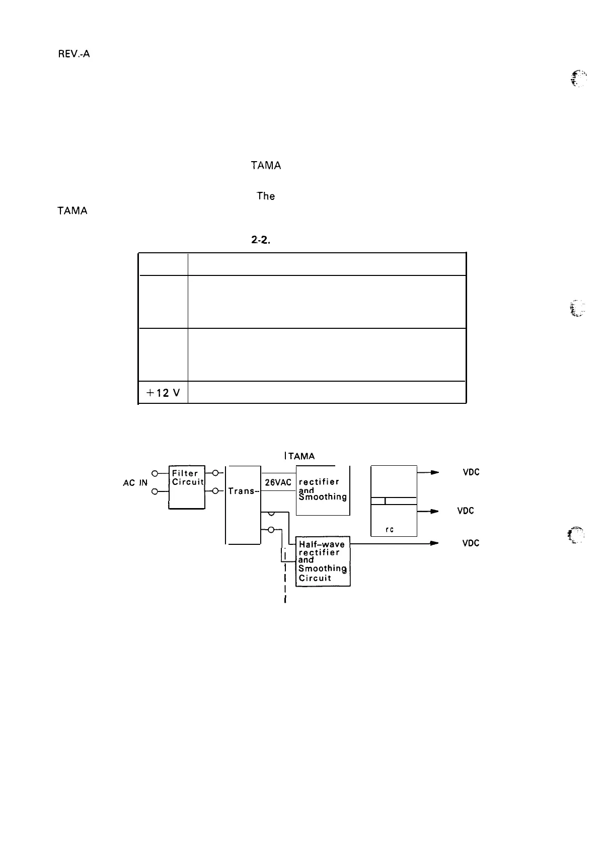
Table
2!-2.
Voltage Applications
Voltage
Purpose
+5 v Logic circuit voltage
Holding voltage for paper feed motor
Others
+24 V Carriage motor drive voltage
Paper-feed motor
drive voltage
Printhead drive voltage
+12V
Voltage for the optional l/F
A block diagram of the power supply circuit is shown in Figure 2-11.
TA Filter Unit
I
TAMA
Board
Step-
*
Full-wave
—
+24
~
+24
VDC
down
26VAC
~;jtifier
Regulator
Trans--
.
—
Circuit
former
I
smo~thiflg
I
I
.
I
Circuit
w
+5
~
+5
vDC
12VAC
Regulator
C i
rc
uit
I
E
+12
VDC
y-l
rectifier
I
~n~oothing
I
Circuit
I
Figure 2-11. Power Supply Circuit Block Diagram
2-1o
 Loading...