EasyManuals Logo

Garmin G5 Installation Manual

Garmin G5
285 pages
To Next Page IconTo Next Page
To Previous Page IconTo Previous Page
Page #219 background imageLoading...
Page #219 background image
Garmin G5 Electronic Flight Instrument Part 23 AML STC Installation Manual 190-01112-10
Rev. 21
Page 219
- CONNECTOR INFORMATION
A.1 G5
A.1.1 J51
Figure 6-7 J51 on the G5
J51 Pin Descriptions
Pin
Pin Name
I/O
1
CAN-H
I/O
2
CAN-L
I/O
3
UNIT ID
In
4
RS-232 RX 1
In
5
RS-232 TX 1
Out
6
SIGNAL GROUND
--
7
AIRCRAFT POWER 1
In
8
AIRCRAFT POWER 2
In
9
POWER GROUND
--
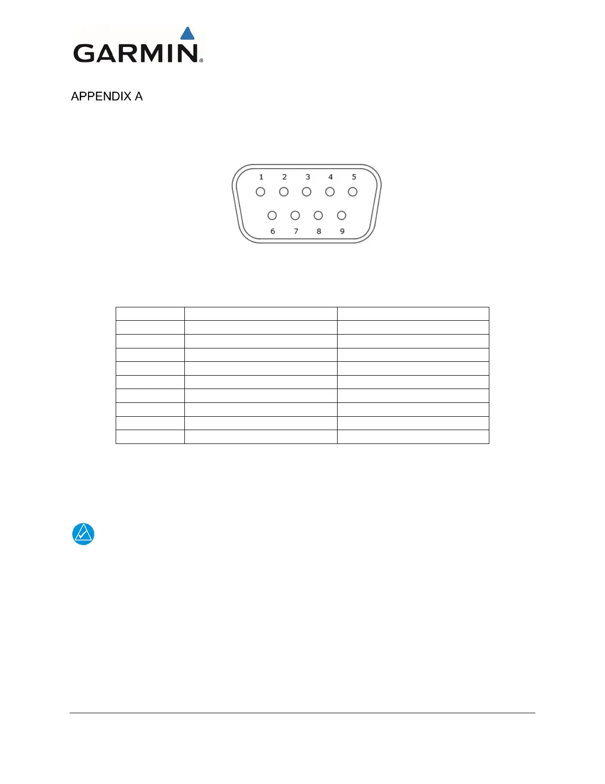
A.1.2 Aircraft Power
The G5 operates using power from one 14 / 28 VDC input. Pin 8 (AIRCRAFT POWER 2) is not used as
a part of this STC.
NOTE
AIRCRAFT POWER 2 is for connecting to an alternate power source, such as on aircraft with
two electrical buses.
A.1.3 RS-232
The G5 has one RS-232 channel that may be used to interface to an existing GPS navigator or GPS
source to receive GPS data for attitude aiding. Also, the G5 RS-232 port can be used to receive
VHF and GPS navigation information.
For specific configuration settings for RS-232 refer to Section 6.3.6.2.
If an existing connection is made to the RS-232 port, the G5 connection can be spliced into the existing
wiring at the connector. For specific wiring information, refer to Section 5.

Table of Contents

Other manuals for Garmin G5

Questions and Answers:

Question and Answer IconNeed help?

Do you have a question about the Garmin G5 and is the answer not in the manual?

Garmin G5 Specifications

General IconGeneral
BrandGarmin
ModelG5
CategoryAvionics Display
LanguageEnglish

Related product manuals