Garmin G5 Electronic Flight Instrument Part 23 AML STC Installation Manual 190-01112-10
Rev. 21
Page 28
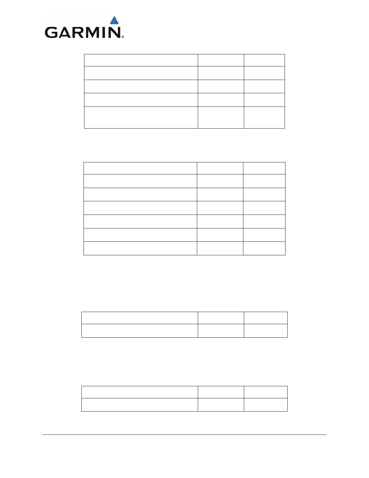
Table 3-3: Contents of the G5, GMU 11, and GAD 13 Connector Kits (011-03002-00/10)
Sub-Assy, Bkshl w/Hdw, Jackscrew, 9 pin
Sub Assy, CAN Termination Kit*
Conn, Rcpt, D-Sub, Crimp Socket, 9 Ckt
Contact, Sckt, D-Sub, Crimp, Size 20, 20-24
AWG
*NOTE: Not all items included in kit P/N 011-02887-00 are used in this installation
The installation kit listed in Table 3-4 is required whenever a GAD 29/29B is installed.
Table 3-4: Contents of the GAD 29/29B Connector Kit (011-03271-00)
Backshell w/Hdw, Jackscrew, 9 Pin
Backshell w/Hdw, Jackscrew, 25 Pin
Conn, Plug, D-Sub, Crimp Pin, 25 Place
Conn, Rcpt, D-Sub, Crimp Sckt, 9 Place
Contact, Socket, Military Crimp, Size 20
Contact, Pin, Military Crimp, Size 20
The item listed in Table 3-5 will be supplied when a G5 DG/HSI is ordered. The adapter plate is
used whenever a G5 is installed and any instrument panel modification has taken place or a G5 is
installed in an instrument hole with cutouts for instrument knobs. Alternatively the installer can field
fabricate the adapter as needed. Reference 4.1.2.4 for installation details.
Table 3-5: G5 Adapter Plate
The item listed in Table 3-6 is optional. It can be ordered from Garmin or fabricated in accordance
with Section 4.1.2.6. The recessed adapter plate is only used when recessing the G5 into the
instrument panel. This same part can be used when installing single or dual recessed G5 units.
Reference 4.1.2.6 for installation details.
Table 3-6: G5 Recessed Adapter Plate
G5 Recessed Adapter Plate

 Loading...


