Garmin G5 Electronic Flight Instrument Part 23 AML STC Installation Manual 190-01112-10
Rev. 21
Page 40
3.4.12.1 Resistor Method B
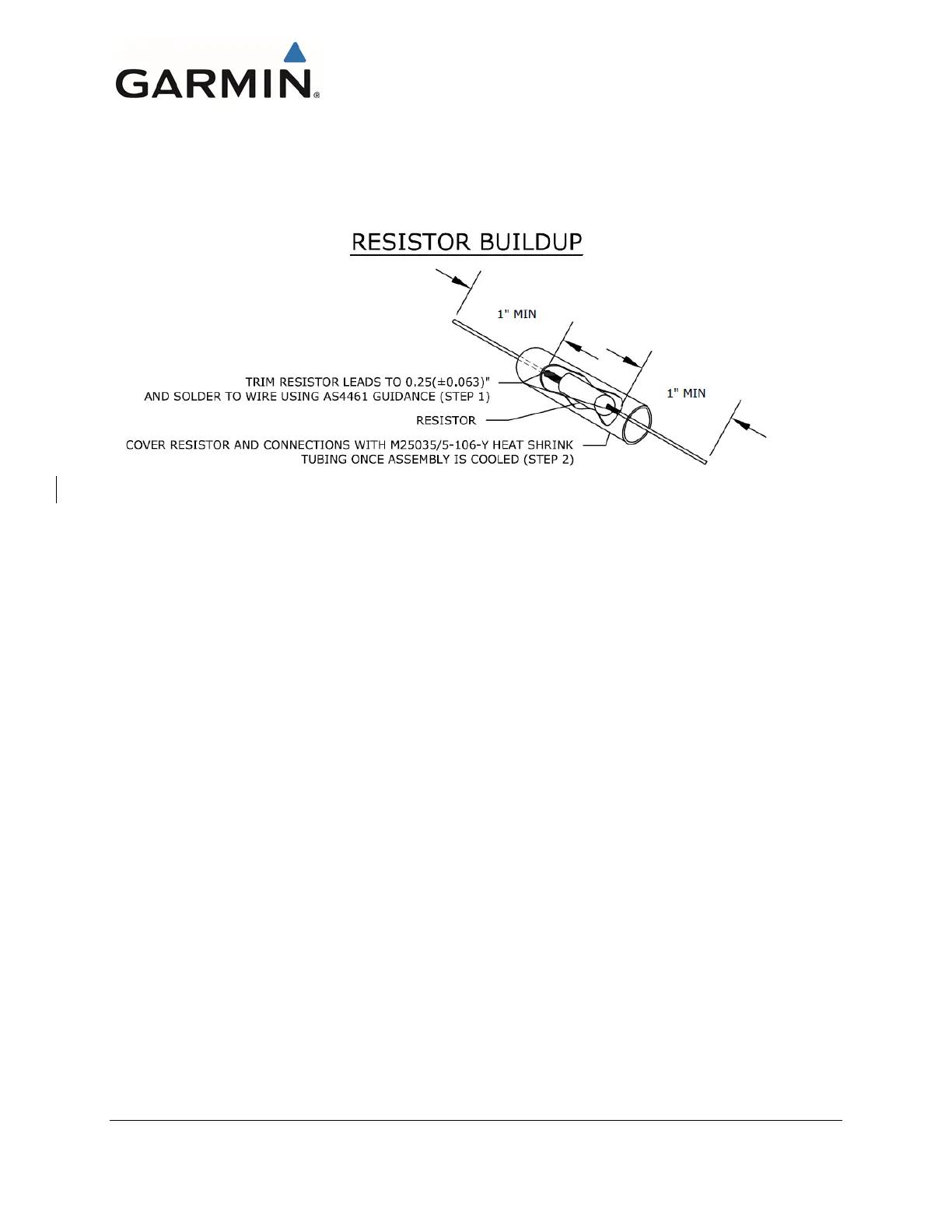
Figure 3-10 shows the preparation procedure for the components into the wiring harness. For part
numbers of resistor, see Section 3.2.1. Figure 3-11 shows the placement requirements of the resistors on
the CAN bus wiring. See Section 5 for complete wiring interconnect details.
Figure 3-10 Method B G5 Resistor Preparation
Steps for component installation:
1. Solder resistor to at least 1” of stranded M22759 wire per SAE AS4461.
Note: Acceptable solder types are SN60 or SN63. Clean flux residues using an appropriate flux
cleaner.
2. Cover component and at least 0.5” of wire on each side of component leads with heatshrink as
shown.
Note: The “-Y” character is for color of heat shrink, color of heat shrink is the installer’s choice.
3. Mark heatshrink with resistor value in permanent ink.

 Loading...


