Garmin G5 Electronic Flight Instrument Part 23 AML STC Installation Manual 190-01112-10
Rev. 21
Page 27
3 INSTALLATION OVERVIEW
3.1 Introduction
The following section contains an overview of the steps required for the installation of the G5 Electronic
Flight Instrument. This section includes requirements for selection of proper locations in the aircraft, as
well as requirements for supporting structure, mechanical alignment and wiring. Any restrictions on
nearby equipment and requirements are also specified.
3.2 Installation Materials
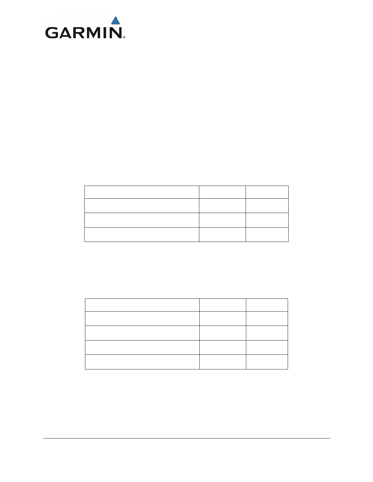
The installation kit listed in Table 3-1 is required for each G5 installation.
Table 3-1: Contents of the G5 Installation Kit (011-03892-00)
*NOTE: Not all items included in kit P/N 011-03002-00 are used in this installation.
The installation kit listed in Table 3-2 is required any time a GMU 11 is installed.
Table 3-2: Contents of the GMU 11 Installation Kit (011-04349-90)
The connector kit P/N 011-03002-10 is required to be ordered separately for a GAD 13 installation. For
the G5 and GMU 11, the connector kit P/N 011-03002-00 is part of the LRU’s associated installation kit.

 Loading...


