Garmin G5 Electronic Flight Instrument Part 23 AML STC Installation Manual 190-01112-10
Rev. 21
Page 243
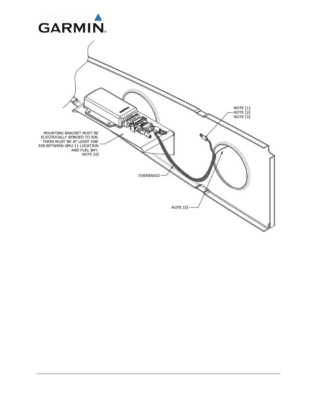
NOTES:
[1] Install #10 grounding hardware in accordance with AC 43.13-1B, section 11-189. If
there is an existing hole located in an appropriate area it may be utilized for the
grounding hardware. If there is no existing hole usable for this purpose then drill and
de-burr a 0.196”-0.206” hole.
[2] MS25036-103 terminal lug (or equivalent).
[3] Terminal lug face or connecting hardware must not interfere with bend radius of rib
edge or stiffened holes. Stud hole must be located a minimum 1” from unstiffened
holes. Refer to SAE AS25036 for lug dimensions.
[4] If the overbraid length is less than 10-inches, no additional bonding strap per Section
4.5 is required. For installations with overbraid length in excess of 10-inches refer to
Section 4.5 for electrical bonding requirements.
[5] The exposed cable not having overbraid in the wing tip areas must be 6 inches or
less. If wiring is not over braided, a bonding strap will need to be installed as
described in section 4.5.
Figure 6-26 GMU 11 Overbraid Termination

 Loading...


