Garmin G5 Electronic Flight Instrument Part 23 AML STC Installation Manual 190-01112-10
Rev. 21
Page 282
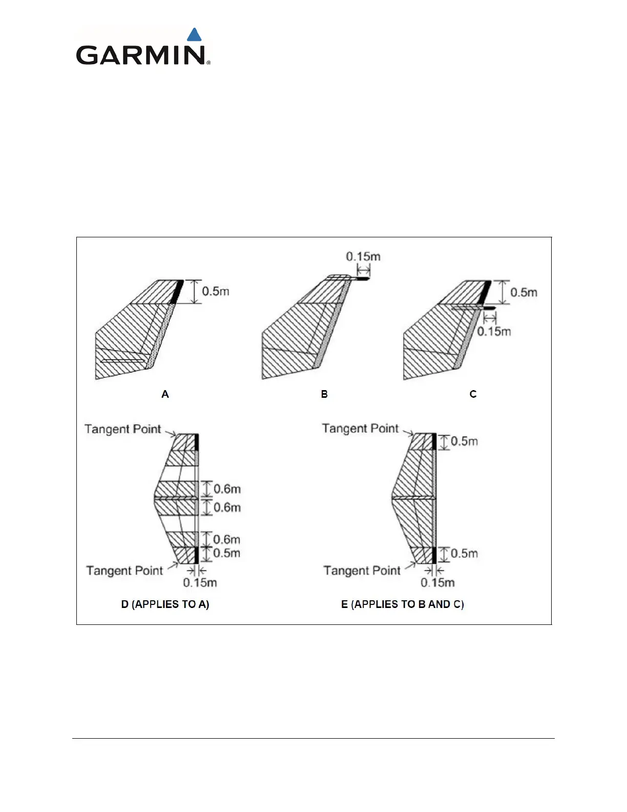
F.1.3 Empennage
If the GTP 59 and GMU 11 cannot be mounted in other areas of the aircraft that are Zone 3 locations, it is
acceptable for metal aircraft with one of the four traditional empennages shown in Figure 6-40 and Figure
6-41 to mount the GTP 59 or GMU 11 in the Zone 2A area of the tail. However, the GTP 59 or GMU 11
cannot be mounted on/under any non-conducting surfaces. If the complete empennage of the aircraft
being considered does not match those shown in Figure 6-40 or Figure 6-41, then it should be mounted in
allowed areas defined for the fuselage and wings. If only portions of the empennage shown below match,
then the same rule applies and the GTP 59 or GMU 11 cannot be installed in the empennage. Note that it
is allowable for only the horizontal stabilizer tips to differ from those shown in Figure 6-40 and Figure
6-41. The GTP 59 cannot be located in the horizontal stabilizer of the empennage. Neither the GTP 59 nor
the GMU 11 can be mounted in the tail of a composite empennage.
Figure 6-40 Zoning for Empennage

 Loading...


