EasyManuals Logo

Garmin G5 Installation Manual

Garmin G5
285 pages
To Next Page IconTo Next Page
To Previous Page IconTo Previous Page
Page #72 background imageLoading...
Page #72 background image
Garmin G5 Electronic Flight Instrument Part 23 AML STC Installation Manual 190-01112-10
Rev. 21
Page 72
Screws
MS35206-XXX (#6, Length A/R)
Washers
NAS1149FN632P
OR
#6
Nutplates
Standard Part; Any MS (Mil-Spec) Part Number
Nuts
MS21044N06
Rivets
MS20426AD3-X
Countersunk Screws
#6 MS24693-XXX
Washers
NAS1149FN632P
Nuts
MS21044N06
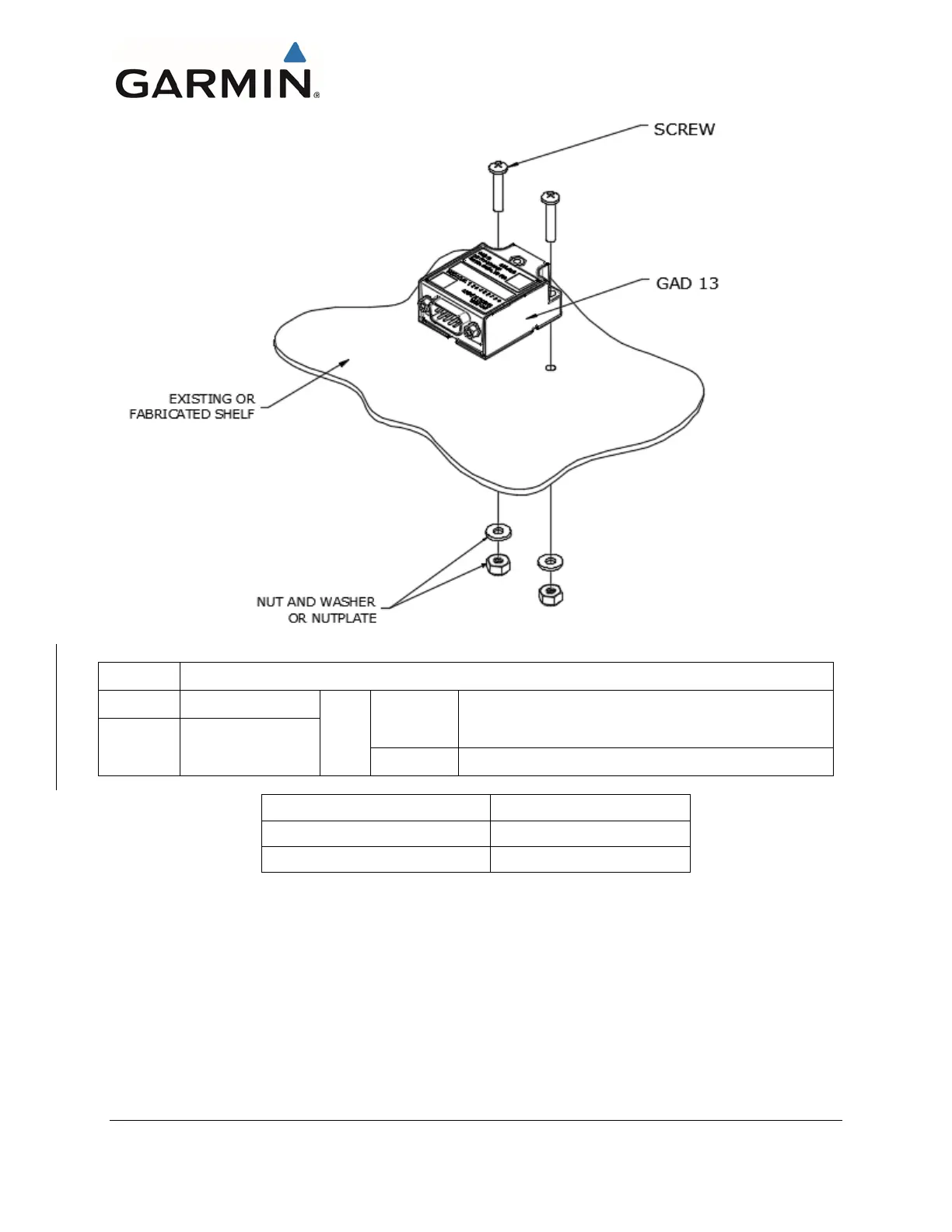
Figure 4-41 GAD 13 Mounting Hardware
4.1.4.1 GAD 29B Transformer Mounting Instructions
Reference Section 3.4.10 for GAD 29B transformer mounting.
4.1.5 Pneumatic Connections
The G5 Attitude indicator and G5 DG/HSI use pitot and static pressure for the secondary display of
altitude and airspeed. The installer must install the necessary hoses and fittings to interface to the existing
aircraft pitot and static pressure source. Below are guidelines to use for this installation.

Table of Contents

Other manuals for Garmin G5

Questions and Answers:

Question and Answer IconNeed help?

Do you have a question about the Garmin G5 and is the answer not in the manual?

Garmin G5 Specifications

General IconGeneral
BrandGarmin
ModelG5
CategoryAvionics Display
LanguageEnglish

Related product manuals