Garmin G5 Electronic Flight Instrument Part 23 AML STC Installation Manual 190-01112-10
Rev. 21
Page 68
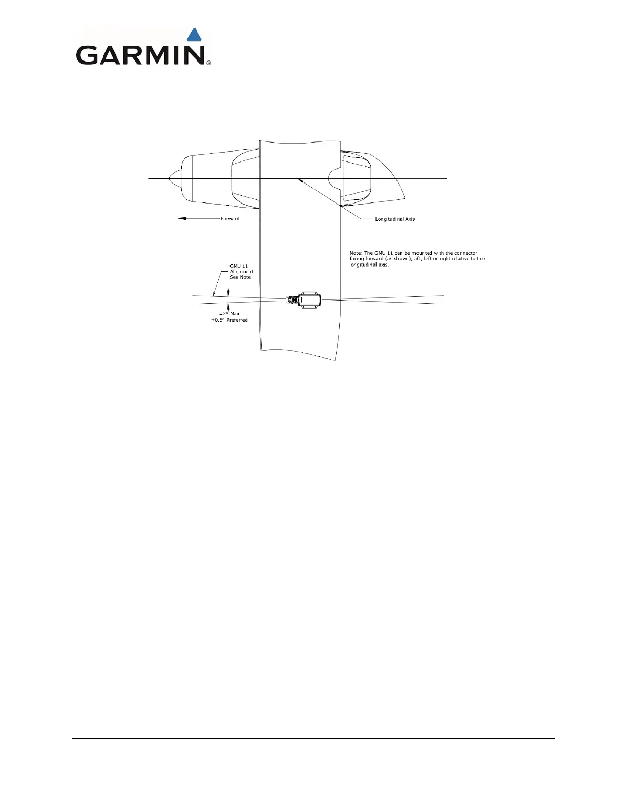
Lateral orientation can be such that the connector faces forward, aft, left or right, but must be within 2° of
the longitudinal axis of the aircraft, see Figure 4-38.
Figure 4-38 GMU 11 Heading Alignment Requirements
4.1.3.1 Magnetic Interference Survey
1. Temporarily place the GMU 11 in the proposed mounting location maintaining orientation as
described in Figure 4-37 and Figure 4-38.
2. Secure in place using tape if needed. Do not use clamps or other devices that are ferrous or
magnetic.
3. Run the magnetic interference survey in accordance with APPENDIX C. If the survey passes, the
location is considered reliable for the installation of the GMU 11.
If the test fails, the location should be considered unreliable until the source of the magnetic interference
is identified, remedied and the location is retested and passes the test. If the magnetic interference cannot
be remedied, another location should be chosen and tested.
This area intentionally blank

 Loading...


