Garmin G5 Electronic Flight Instrument Part 23 AML STC Installation Manual 190-01112-10
Rev. 21
Page 224
A.3.7 Autopilot Heading/Course (GAD 29B Only)
The GAD 29B can provide analog heading and course error outputs to third-party analog autopilots. In
the case of an AC autopilot, the GAD 29B has an AC REFERENCE signal input.
For specific wiring information, refer to Section 5.
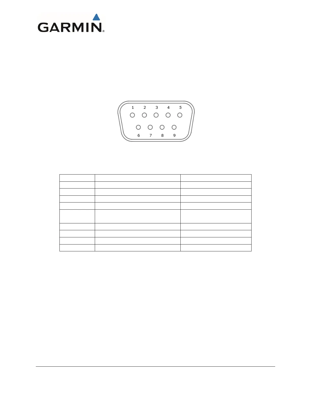
A.4 GAD 13
A.4.1 J131
Figure 6-11 J131 on the GAD 13
J131 Pin Descriptions
A.4.2 Aircraft Power
The GAD 13 operates using power from one 14 / 28 VDC input.
A.4.3 CAN Bus
The GAD 13 CAN bus conforms to the BOSCH standard for Controller Area Network (CAN) 2.0-B
and ISO 11898. See Section 3.4.5.2 for details. The CAN bus connection on the GAD 13 is used to
connect the GAD 13 to one or two G5s, a GMU 11, and a GAD 29/29B.
For specific wiring information. refer to Section 5.
A.4.4 OAT Probe Interface
The GAD 13 has three pins for interface to a passive (RTD type) and two pins for interface to an active
OAT probe. This interface provides excitation voltage/current, and temperature sensing capabilities for a
OAT probe. For specific wiring information, refer to Section 5.

 Loading...


