Garmin G5 Electronic Flight Instrument Part 23 AML STC Installation Manual 190-01112-10
Rev. 21
Page 92
o Audio Panel
o Stall Warning System (if applicable)
o Pitot Heat
o Landing Light (switched on during landing only)
o Instrument Panel Dimming
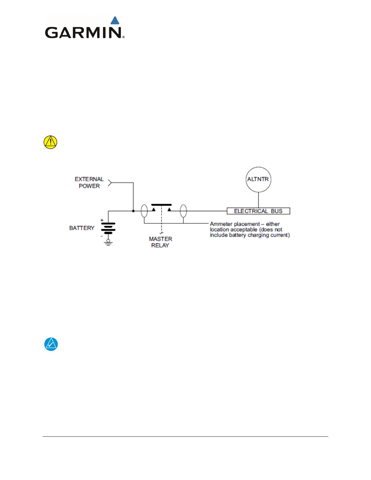
6. Insert/attach the ammeter in the line from the external power source to the master relay circuit
as shown in Figure 4-51. This will eliminate errors due to the charging current drawn by the
battery.
CAUTION
To avoid damage to equipment, ensure the ammeter is capable of handling the expected load.
Figure 4-51 Ammeter Placement for Current Measurements
7. Ensure all circuit breakers are closed.
8. Apply external power to the aircraft. The voltage of the power source should be set to the
nominal alternator voltage (usually 13.8 VDC or 27.5 VDC).
9. Turn on the battery master switch.
NOTE
Intermittent electrical loads are not measured. It is assumed if additional current is required
beyond what the alternator can supply, this short-duration demand will be provided by the
battery.
10. Set the lighting as described below. These settings will be used for every current
measurement which follows:
o Set instrument panel and flood lights to maximum brightness.
o Set displays with a backlight to 50% brightness

 Loading...


