Garmin G5 Electronic Flight Instrument Part 23 AML STC Installation Manual 190-01112-10
Rev. 21
Page 87
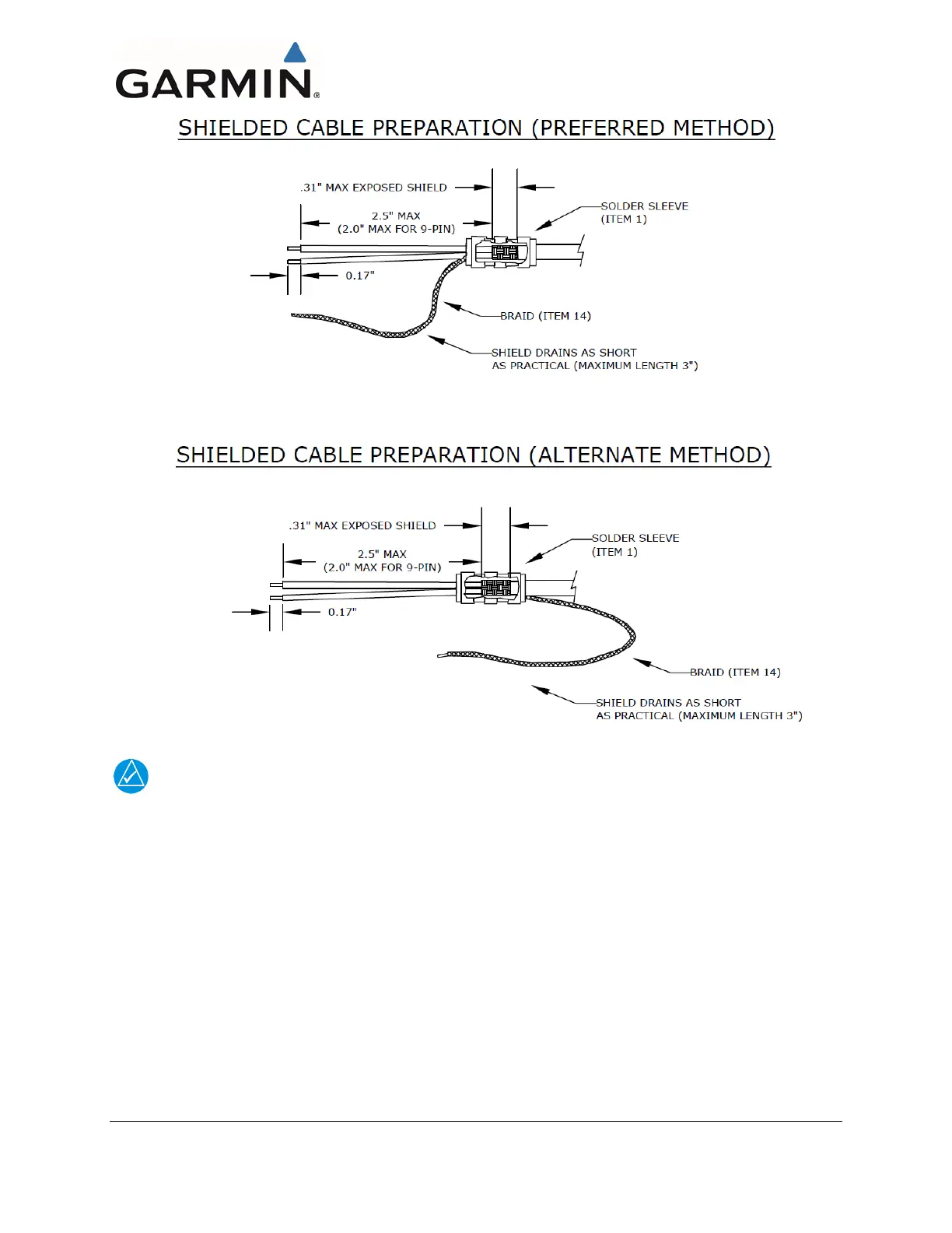
Figure 4-50 Shield Termination Methods
NOTE
Max length of shield drain (braid) = 3.0 inches. If a splice requires extra length, max length of
unshielded wire = 4.0 inches and max length of shield drain (braid) = 3.0 inches. It is acceptable
to use shorter lengths.
Prepare all of the shielded wires using one of the shield termination methods shown in Figure 4-50.
Keep the shield drains as short as practical (3” max total length). See Table 4-4, Table 4-5, and Table
4-6 regarding numbers in parentheses in the following procedure.
1.
Strip 2.5 inches (maximum) (2.0 inches maximum for 9-pin connectors) of the jacket to expose
the shield braid.
2.
Remove the exposed braid.
3.
Carefully score the jacket 1/4 to 5/16 inches and remove the jacket to leave the braid exposed.
4.
Slide a shield terminator (1) onto the exposed shield braid and insert shield braid drain (14) into
shield terminator. Secure the shield terminator and braid drain to the shield using a heat gun
approved for use with solder sleeves.

 Loading...


