Garmin G5 Electronic Flight Instrument Part 23 AML STC Installation Manual 190-01112-10
Rev. 21
Page 57
4.1.2.6.4 Instrument Panel Modification Limitations
The modification required for recess mounting a G5, whether it is single, dual vertical or dual horizontal
must meet the following conditions:
1) The mounting location must satisfy the alignment requirements shown in Figure 4-3, Figure 4-4,
Figure 4-5.
2) The proposed location must allow for sufficient clearance for the G5 unit and connections as
shown in Figure 4-14.
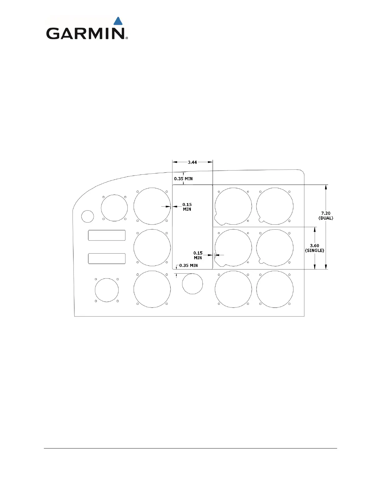
3) The hole must meet the limitations and minimums as shown in Figure 4-22.
4) The modification must be completed in accordance with AC 43.13-2B, Chapter 2.
Any modification of subsequent structure or parts other than the instrument panel as defined in these
instructions are beyond the scope of this manual. Additional data from the aircraft manufacturer or other
FAA approved data would be required for these situations.
Figure 4-22, Instrument Panel Limitations
4.1.2.6.5 Modifying Recess Mount Adapter Plate
This section illustrates a suggested procedure for modifying the G5 Recessed Adapter Plate and
instrument panel. Dual vertical G5 installation shown; dual horizontal and single installation procedure is
similar.

 Loading...


