Garmin G5 Electronic Flight Instrument Part 23 AML STC Installation Manual 190-01112-10
Rev. 21
Page 76
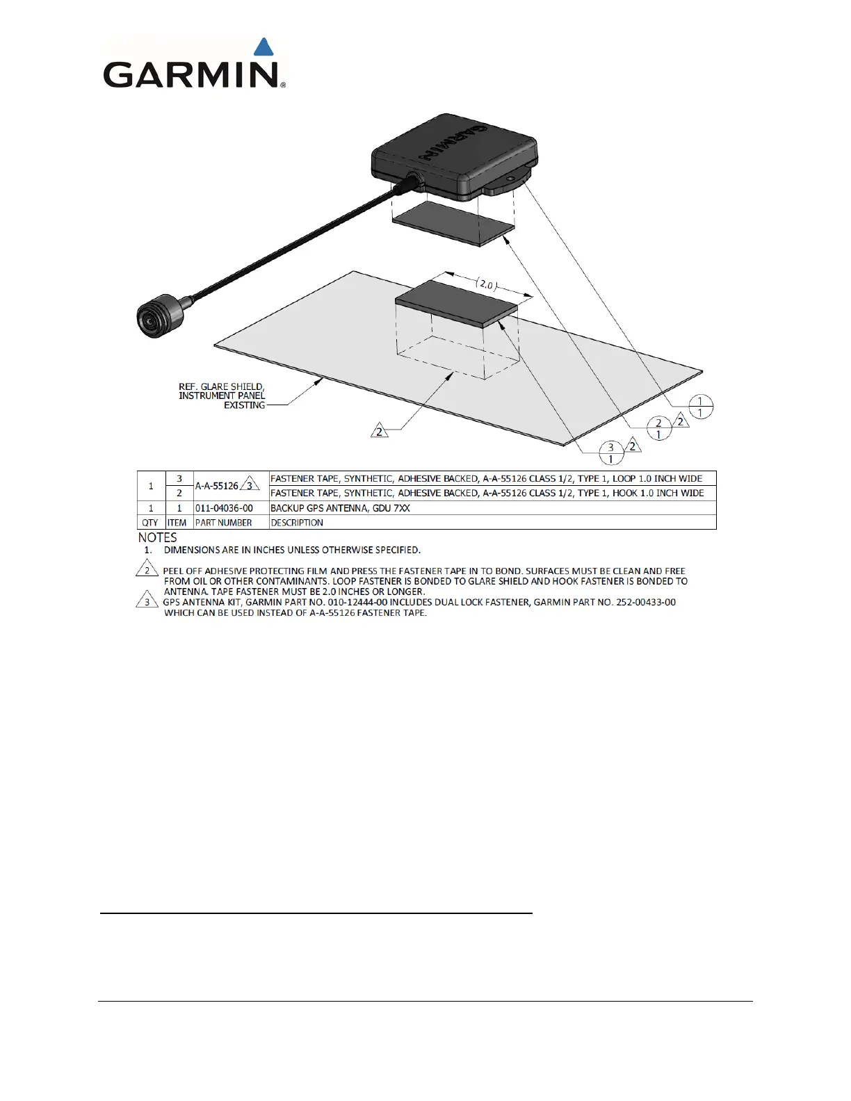
Figure 4-44 – Glare Shield Mounted GPS Antenna (Hook & Loop Installation Example)
4.1.7 GTP 59 Mounting
An effective location for the GTP 59 OAT Probe is on or near an access panel on the bottom of the wing,
or in areas where it would mostly be shaded in straight and level flight. A typical installation example is
shown in Figure 4-46.
The GTP 59 probe has no icing protection. Temperature measurements may be incorrect if ice
accumulates on the probe, which in turn may affect computations of true airspeed, delta-ISA, or other
data that depends on the measurement of air temperature.
The GTP 59 cannot be mounted on or near a control surface. Control surfaces include but are not limited
to ailerons, elevators, rudder, trim tabs and speed brakes.
GTP 59 Probe Installation in Metal and Tube-and-Fabric Aircraft
For metal and tube-and-fabric aircraft, the electrical bond between GTP 59 and nearby aircraft metallic
structure (tubular structure in the case of tube and fabric aircraft) must achieve a direct current (DC)
resistance less than or equal to 2.5 mΩ with the remote end connector disconnected. The GTP 59 can only
be installed in lightning zones 2A or 3, per APPENDIX F.

 Loading...


