CHAPTER 4: SETPOINTS OUTPUTS
845 TRANSFORMER PROTECTION SYSTEM – INSTRUCTION MANUAL 4–127
Outputs
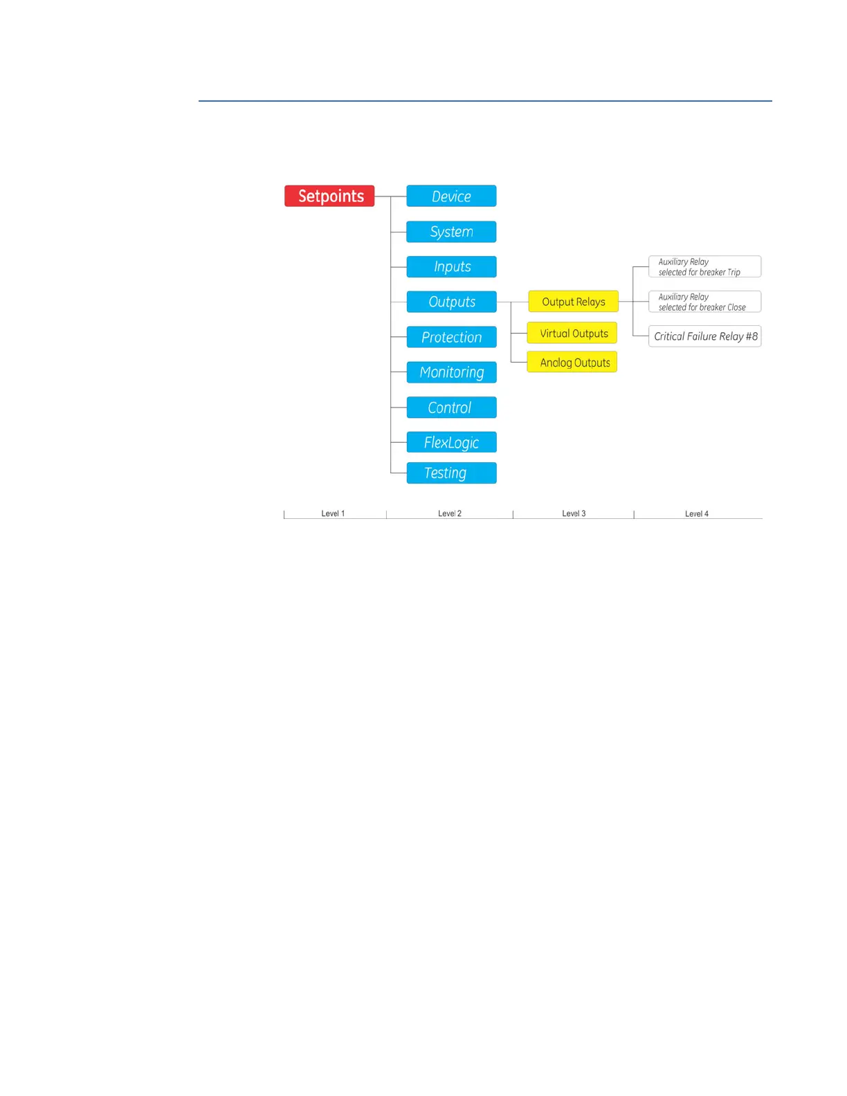
Figure 4-38: Outputs Display Hierarchy
Output Relays
The 845 Transformer Protection System relay is equipped with a number of
electromechanical output relays specified at the time of ordering. The I/O module from slot
F, for example, provides five output relays.
The 845 auxiliary relays, starting with Aux. Relay 1, can be energized from the menu of
each protection or control feature, or from their respective menus when assigning a
FlexLogic operand (trigger) under the setpoint "Aux Rly # Operate".
The auxiliary relays can be used for different applications. Any output relays can be
programmed for either tripping or closing a breaker. For each of the breakers, a pair of
auxiliary relays can be selected for tripping and closing. Depending on how an Aux. Relay
is assigned, one of the following output relay logic diagrams applies:
1. If the auxiliary output relay is programmed under the Breaker menu for breaker
tripping, the operation of the output follows the Trip logic diagram below.
2. If the auxiliary output relay is programmed under the Breaker menu for breaker
closing, the operation of the output follows the Close logic diagram.
3. If the auxiliary output is not programmed for tripping or closing a breaker, the
operation of the output follows the Auxiliary Relay Generic logic from logic diagram.
The Trip and Close auxiliary relays follow the respective Trip and Close logic, meaning they
will have fixed operating characteristics as they depend on breaker feedback for resetting.
The auxiliary relays selected for breaker tripping are also available for selection from the
menus of all protection elements. The auxiliary relays selected for breaker closing are
excluded from the list for selection from the menu of all elements. Refer to the Breaker
setup section on how to select an auxiliary relay for breaker trip and close.
The operation of output relays selected for breaker Trip and breaker Close are breaker-
controlled relays designed to be controlled by the state of the breaker as monitored by a
52a contact, 52b contact, or both.

 Loading...