3–10 845 TRANSFORMER PROTECTION SYSTEM – INSTRUCTION MANUAL
FRONT CONTROL PANEL INTERFACE CHAPTER 3: INTERFACES
target setting is “Latched”, then the corresponding Event Cause LEDs turn ON when the
operate operand associated with the element is asserted and will remain ON until the
RESET button on the front panel is pressed after the operand is reset.
Default labels are shipped in the package of every 845, together with custom templates. A
custom LED template is available for editing and printing, refer to publication GET-20035
from
http://www.gegridsolutions.com/multilin. The default labels can be replaced by user-
printed labels. User customization of LED operation is of maximum benefit in installations
where languages other than English are used to communicate with operators.
FAST PATH:
For LED and Pushbutton programming details, please refer to Front Panel.
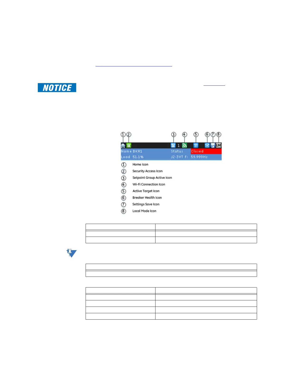
Home Screen Icons
The next figure shows the icons available on the front screen. For descriptions of these
screen icons see the following tables.
Figure 3-11: Home Screen Icons
Table 3-1: Security Icon
NOTE:
The security icon only represents the security access level through the front panel.
Table 3-2: Setpoint Group Icon
Table 3-3: Wifi Icon
Security State Security Icon Color
User not logged in Icon is green and locked
User logged in Icon is red and unlocked
Description
Identifies the active setpoint group
Wifi State Wifi Icon Color
Disabled Icon is grey and crossed by a red line
Disconnected Grey
Connecting Orange
Connected Green

 Loading...