CHAPTER 2: INSTALLATION ELECTRICAL INSTALLATION
845 TRANSFORMER PROTECTION SYSTEM – INSTRUCTION MANUAL 2–25
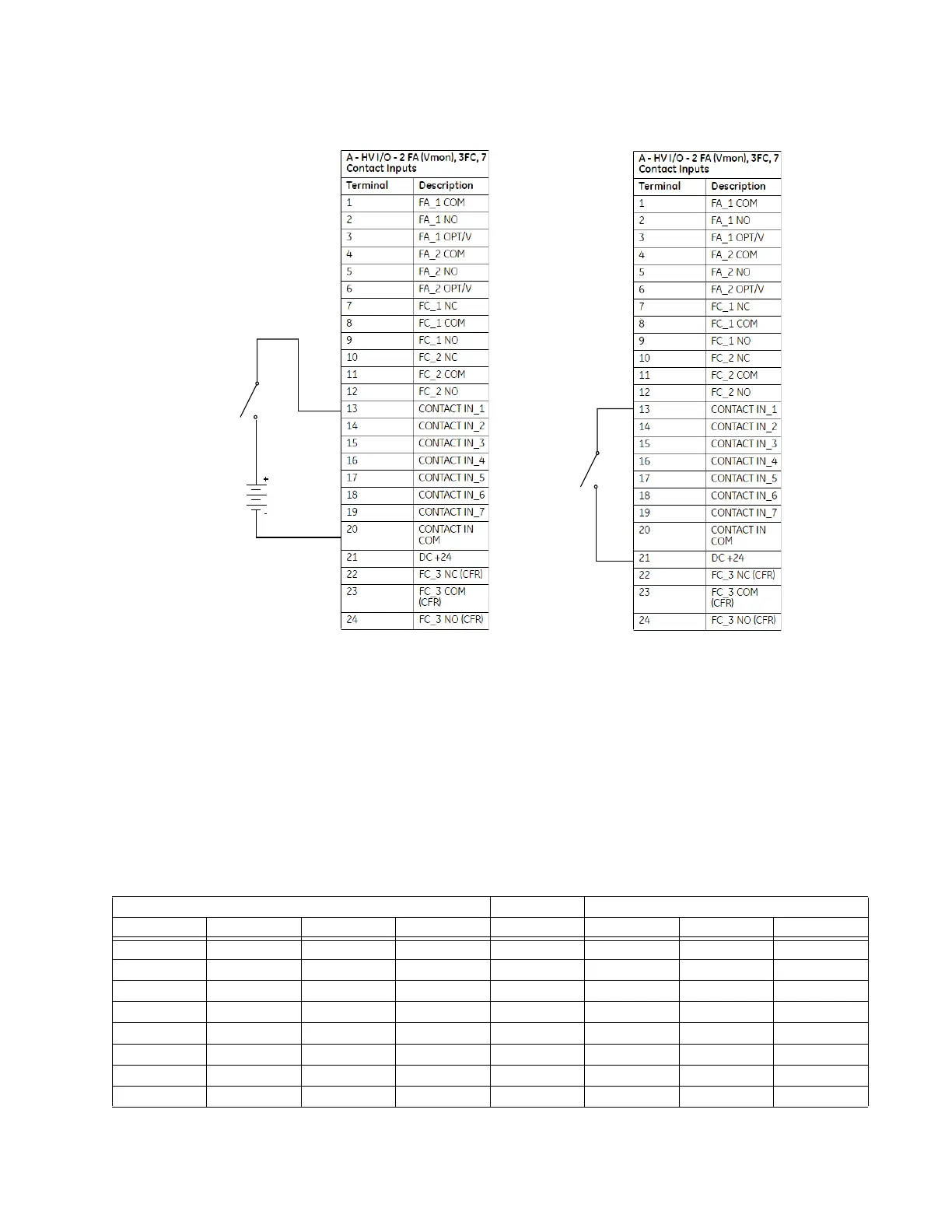
Figure 2-28: Wet and Dry Contact Input Wiring Examples
Output Relays
The locations of the output relays have a fixed assignment for the platform called the
master identifier. I/O options that include inputs occupy the fixed assigned output
locations so in these cases the relay assignment maps to the master identifier.
The output relays for the 845 relay are fully programmable, and can be assigned in the
transformer breakers menu for breaker tripping or closing. The output relays assigned for
breaker closing, are automatically excluded from the menus for output selection for the
rest of the elements.
The critical failure output relay is reserved as Relay_8 and it is omitted and is not
programmable.
Table 2-6: Slots F,G,H Terminal Master Identifier (left) and I/O options A,A,N (right)
INPUT
SIGNAL
SWITCH
(DRY)
INPUT
SIGNAL
SWITCH
(WET)
EXTERNAL
DC POWER
SUPPLY
Slots F,G,H Terminal Master Identifier Slots F,G,H with I/O options A,A,N
Terminal # SLOT F SLOT G SLOT H Terminal # SLOT F SLOT G
1 RELAY_1 RELAY_9 RELAY_17 1 RELAY_1 RELAY_9
2 RELAY_1 RELAY_9 RELAY_17 2 RELAY_1 RELAY_9
3 RELAY_1 RELAY_9 RELAY_17 3 RELAY_1 RELAY_9
4 RELAY_2 RELAY_10 RELAY_18 4 RELAY_2 RELAY_10
5 RELAY_2 RELAY_10 RELAY_18 5 RELAY_2 RELAY_10
6 RELAY_2 RELAY_10 RELAY_18 6 RELAY_2 RELAY_10
7 RELAY_3 RELAY_11 RELAY_19 7 RELAY_3 RELAY_11
8 RELAY_3 RELAY_11 RELAY_19 8 RELAY_3 RELAY_11

 Loading...