5–8 845 TRANSFORMER PROTECTION SYSTEM – INSTRUCTION MANUAL
VIRTUAL OUTPUTS CHAPTER 5: STATUS
Virtual Outputs
Path: Status > Virtual Outputs
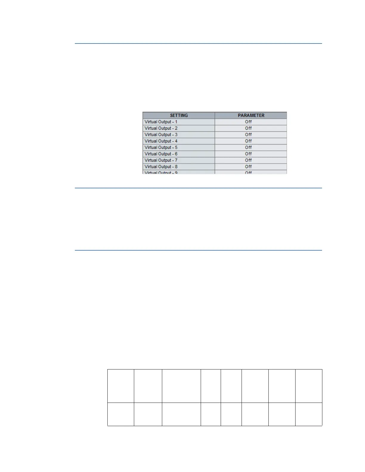
The state of all virtual outputs is shown here, see next figure. The value for each Virtual
Output is shown on the control panel graphically as a toggle switch in either the On (|) state
or the Off (O) state.
Figure 5-6: Status of Virtual Outputs
Flex State
Path: Status > Flex States
There are 256 Flex state bits available. The status value indicates the state of the given Flex
state bit.
Communications
GOOSE Rx and Tx
The 845 supports 3 GOOSE transmissions and 8 GOOSE receptions each with 64 items per
transmission or reception. Non-structured GOOSE is supported. Each item within the
GOOSE message can be a digital or analog value. Messages are launched within one scan
of a digital point status change or an analog exceeding its deadband.
The 845 server supports a subset of the server features described in part 7.2 of the
IEC61850 standard.
GOOSE MESSAGING
As indicated above, the 845 supports 3 GOOSE transmissions and eight GOOSE receptions
as shown in the table below:
Service Launch
Speed*
Support for
Programmable
time to live
# of Tx # of Rx Test Bit
Support
Number of
items in
each
transmissi
on or
reception
Number of
remote
inputs per
relay
Configurab
le GOOSE
Within 2 ms
(1 CPU
scan)*
Time to live
programmable
from 1000 to
60000 ms
38
Devices
Y64 Data
Items per
Data Set
32

 Loading...