CHAPTER 2: INSTALLATION MECHANICAL INSTALLATION
845 TRANSFORMER PROTECTION SYSTEM – INSTRUCTION MANUAL 2–7
Draw-out Unit Withdrawal and Insertion
Unit withdrawal and insertion may only be performed when control power has been
removed from the unit.
FAST PATH:
Turn off control power before drawing out or re-inserting the relay to prevent mal-
operation.
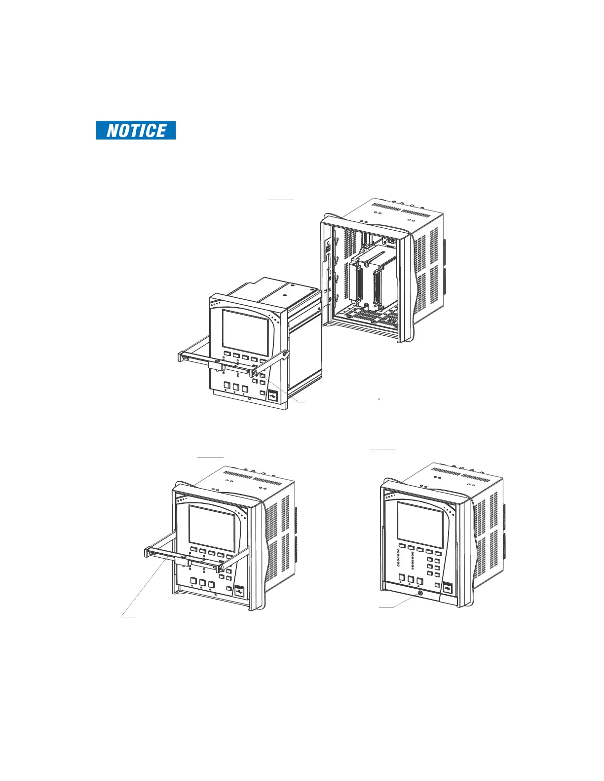
Follow the steps outlined in the diagrams below to insert and withdraw the Draw-out unit.
Figure 2-9: Unit withdrawal and insertion diagram
67(3
6&$/(
67(3
+$1'/(72%(/,)7('72
326,7,21:+,/(6/,',1*
'5$:28781,7,172
&$37,9(81,7
67(3
0$,17$,1+$1'/(/,)7('326,7,21
817,/'5$:28781,7
,6)8//<,16(57('
386++$1'/('2:1
$1'7,*+7(17+(6&5(:
:,7+,1/%72548(
+$1'/(6+28/'%()/86+
:,7+)52173$1(/685)$&(

 Loading...