4–184 845 TRANSFORMER PROTECTION SYSTEM – INSTRUCTION MANUAL
PROTECTION CHAPTER 4: SETPOINTS
Ground Directional
Overcurrent
Protection (67G)
The 845 Ground Directional Overcurrent protection element. It provides both forward and
reverse fault direction indications: the Gnd Dir OC FWD and Gnd Dir OC REV operands,
respectively. The output operands are asserted if the magnitude of the operating current is
above a Pickup level (overcurrent unit) and the fault direction is seen as forward or reverse,
respectively (directional unit).
The overcurrent unit responds to the magnitude of a fundamental frequency phasor of
the ground current. There are separate Pickup settings for the forward-looking and
reverse-looking functions.
The following tables define the Ground Directional Overcurrent element.
The directional unit uses the ground current (Ig) for fault direction discrimination, and can
be polarizing, by either “Calculated V0” zero-sequence voltage or “Measured VX” zero
sequence voltage. The following tables define the ground directional overcurrent element.
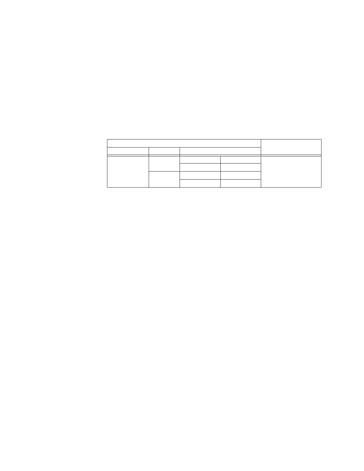
Table 4-34: Quantities for Ground Current Configuration
Where:
V_0 = 1/3 * (Vag + Vbg + Vcg) = zero sequence voltage
When POLARIZING VOLTAGE is set to “Measured VX,” one-third of this voltage is used in
place of V_0. The following figure explains the usage of the voltage polarized directional
unit of the element by showing the voltage-polarized phase angle comparator
characteristics for a phase A to ground fault, with:
ECA = 90° (element characteristic angle = centerline of operating characteristic)
FWD LA = 80° (forward limit angle = the ± angular limit with the ECA for operation)
REV LA = 80° (reverse limit angle = the ± angular limit with the ECA for operation).
The element incorporates a current reversal logic: if the reverse direction is indicated for at
least 1.25 of a power system cycle, the prospective forward indication will be delayed by
1.5 of a power system cycle. The element is designed to emulate an electromechanical
directional device. Larger operating and polarizing signals will result in faster directional
discrimination bringing more security to element operation.
The forward-looking function is designed to be more secure as compared to the reverse-
looking function, and should therefore be used for the tripping direction. The reverse-
looking function is designed to be faster as compared to the forward-looking function and
should be used for the blocking direction. This allows better protection coordination.
The above bias should be taken into account when using the Ground Directional
Overcurrent element to directionalize other protection elements.
Directional Unit Overcurrent Unit
Polarizing Mode Direction Compared Phasors
Voltage Forward -V_0 Ig GROUND CURRENT (Ig)
-V_0 = 1/3 (Vx) Ig
Reverse -V_0 -Ig
-V_0 = 1/3 (Vx) -Ig

 Loading...