4–160 845 TRANSFORMER PROTECTION SYSTEM – INSTRUCTION MANUAL
PROTECTION CHAPTER 4: SETPOINTS
T
RESET
= reset time in seconds (assuming energy capacity is 100% and RESET is
“Timed”)
Table 4-33: I
4
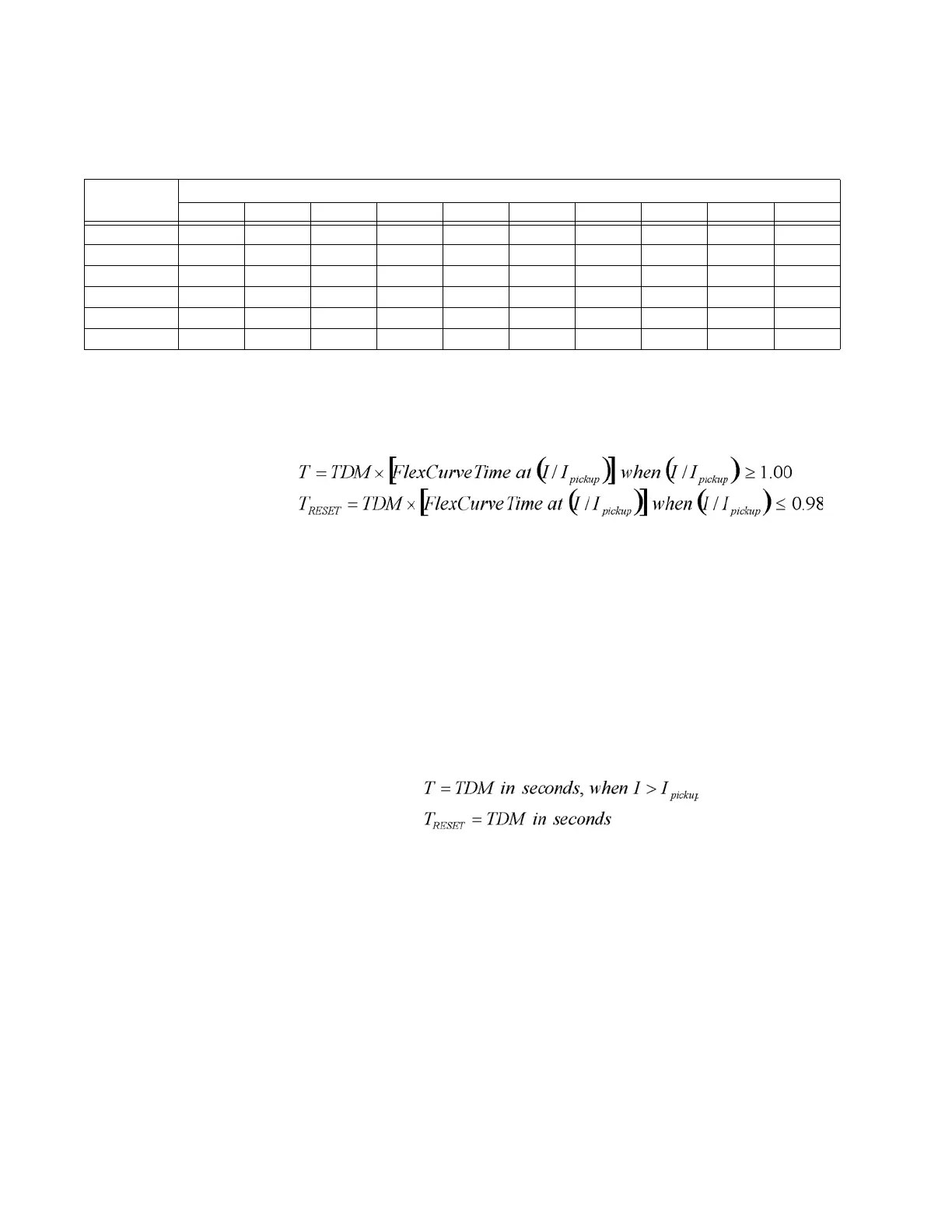
T CURVE TRIP TIMES (IN SECONDS)
FLEXCURVES
The custom FlexCurves are described in detail in the FlexCurves section of this chapter.
The curve shapes for the FlexCurves are derived from the formulae:
Where:
T = operate time (in seconds),
TDM = Multiplier setting,
I = input current,
I
pickup
= Pickup Current setting,
T
RESET
= reset time in seconds (assuming energy capacity is 100% and RESET is
“Timed”)
DEFINITE TIME CURVES
The Definite Time curve shape operates as soon as the Pickup level is exceeded for a
specified period of time. The base Definite Time curve delay is in seconds. The curve
multiplier of 0.05 to 600 makes this delay adjustable from 50 to 600000 milliseconds.
Where:
T = operate time (in seconds)
TDM = Multiplier setting
I = input current
I
pickup
= Pickup Current setting
T
RESET
= reset time in seconds (assuming energy capacity is 100% and RESET is
“Timed”)
Percent of Load-To-
Trip
The Percent of Load-to-Trip is calculated from the phase with the highest current reading.
It is the ratio of this current to the lowest pickup setting among the phase time and the
instantaneous overcurrent elements. If all of these elements are disabled, the value
displayed is “0”.
MULTIPLIER
(TDM)
CURRENT (I/I
pickup
)
1.5 2.0 3.0 4.0 5.0 6.0 7.0 8.0 9.0 10.0
0.01 0.1975 0.0625 0.0123 0.0039 0.0016 0.0008 0.0004 0.0002 0.00015 0.0001
0.10 1.9753 0.6250 0.1235 0.0391 0.0160 0.0077 0.0042 0.0024 0.0015 0.0010
1.00 19.753 6.250 1.235 0.391 0.160 0.077 0.042 0.024 0.015 0.010
10.00 197.531 62.500 12.346 3.906 1.600 0.772 0.416 0.244 0.152 0.100
100.00 1975.31 625.00 123.46 39.06 16.00 7.72 4.16 2.44 1.52 1.00
600.00 11851.9 3750.0 740.7 234.4 96.00 46.3 25.0 14.65 9.14 6.00

 Loading...