CHAPTER 2: INSTALLATION ELECTRICAL INSTALLATION
845 TRANSFORMER PROTECTION SYSTEM – INSTRUCTION MANUAL 2–21
Phase Sequence and Transformer Polarity
For correct operation of the relay features, follow the instrument transformer polarities,
shown in the Typical Wiring Diagram above. Note the solid square markings that are
shown with all instrument transformer connections. When the connections adhere to the
drawing, the arrow shows the direction of power flow for positive watts and the positive
direction of vars. The phase sequence is user programmable for either ABC or ACB rotation.
The 845 relay has four (4) current inputs in each J slot and K slot. Three of them are used
for connecting to the phase CT phases A, B, and C. The fourth input is a ground input that
can be connected to either a ground CT placed on the neutral from a Wye connected
transformer winding, or to a “donut” type CT measuring the zero sequence current from a
grounded system. The relay CTs are placed in a packet mounted to the chassis of the
845
relay. There are no internal ground connections on the current inputs. Current
transformers with 1 to 12000 A primaries may be used.
CAUTION:
Verify that the relay’s nominal input current of 1 A or 5 A matches the secondary rating
of the connected CTs. Unmatched CTs may result in equipment damage or inadequate
protection.
CAUTION:
IMPORTANT: The phase and ground current inputs correctly measure up to 46 times the
current input’s nominal rating. Time overcurrent curves become horizontal lines for
currents above 20 × PKP.
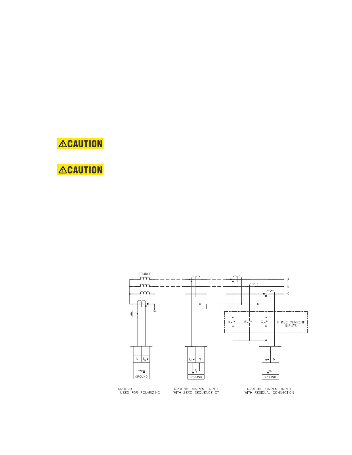
Ground CT Inputs
Before making ground connections, be aware that the relay automatically calculates the
neutral (residual) current from the sum of the three phase current phasors. The following
figures show three possible ground connections using the ground current input (Terminals
J7 and J8).
The ground input (Terminals J7 and J8) is used in conjunction with a Zero Sequence CT as
source, or in the neutral of wye-connected source CTs. The ground current input can be
used to polarize the neutral. When using the residual connection, set the
GROUND
CT PRIMARY setpoint to a value equal to the PHASE CT PRIMARY setpoint.
Figure 2-23: Ground Inputs
892773A2.cdr
8 Series
J1
J2
J3
J4
J5
J7
J6
J8J7 J8J8 J7

 Loading...