6-28 ApexPro™ 2001989-351A
Replaceable parts
4. Remove all quad receiver modules.
5. Remover 6 screws from chassis front.
6. Using a short screwdriver loosen 2 screws inside the receiver cage.
7. Pull chassis front straight out.
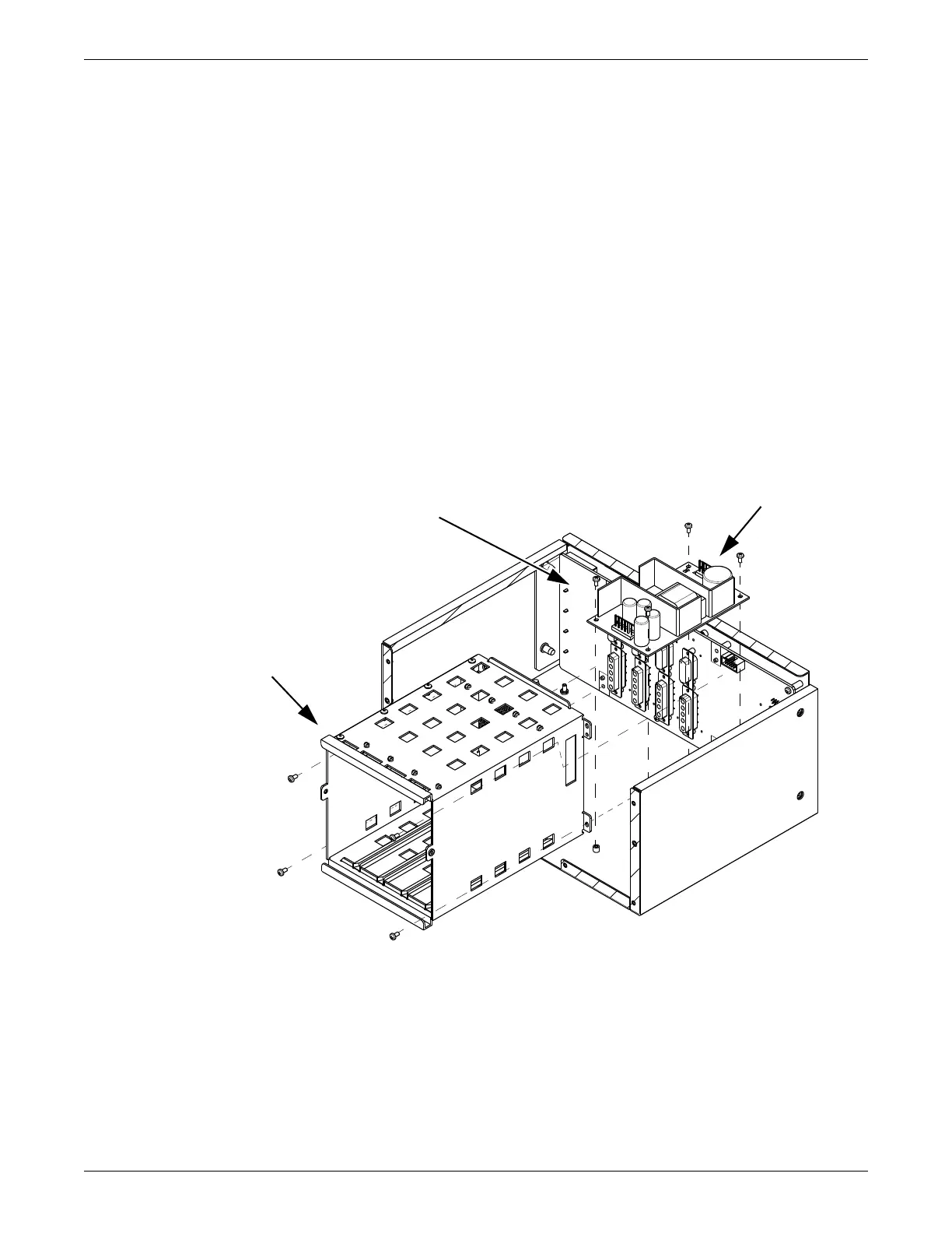
8. Using a long screwdriver remove 4 screws holding receiver cage to receiver
subsystem pcb.
9. Remove receiver cage.
10. Disconnect the power supply harness from the receiver subsystem pcb.
11. At the outside rear of the chassis assembly remove 4 hex nuts and washers.
12. Remove 7 screws holding pcb to chassis assembly.
13. Remove the receiver subsystem pcb.
14. Reverse the above steps to install a receiver subsystem pcb.
Close and reconnect unit
1. Position the front cover and install 2 screws.
2. Reconnect the power cord and all communication cables.
Receiver subsystem pcb
Power supply assembly
Receiver cage
 Loading...


