5-10 ApexPro™ 2001989-351A
Troubleshooting
below the transmitter’s modulated output, otherwise the signal will interfere with the
modulated output and cause drop-out. This test verifies that the carrier level conforms
to this requirement. This test is not required for ApexPro CH transmitters (PN
2014748-XXX).
NOTE
The ApexPro transmitter troubleshooting tree on page 5-4 references this test.
Equipment needed
Spectrum Analyzer (Rohde & Schwarz FSH3 preferred)
N-connector-to-BNC-connector adapter (attached)
BNC-connector-to-F-connector adapter
Cable with F-connectors on both ends, to connect the antenna system output to
the spectrum analyzer input
ApexPro transmitter (PN 418500-XXX)
Rubber duck antenna
Rohde & Schwarz FSH3 test procedure
For each transmitter, perform the following test.
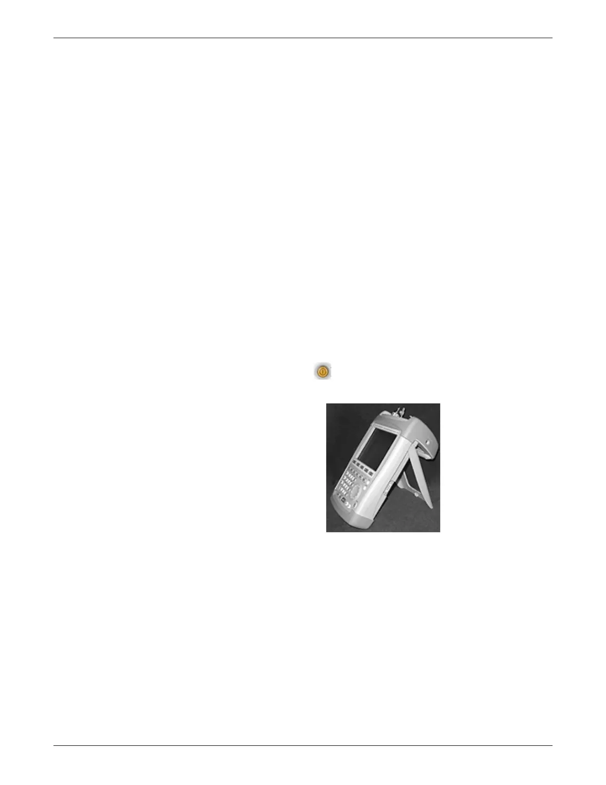
1. Press POWER ON and allow the spectrum analyzer to warm up.
2. Stand the analyzer on end with the stand on back of the analyzer.
3. Attach a rubber duck antenna to the analyzer.
4. Press PRESET.
5. Turn on the transmitter under test. Disconnect any attached leadwires. Wait 10
seconds for the transmitter to stop transmitting.
6. Set the center frequency of the analyzer to the frequency of the transmitter under
test.
a. Press FREQ.
b. Press the numbers corresponding to the center frequency for the channel
being tested and press ENTER.
7. Set the analyzer span to 25 kHz.
 Loading...


