2-12 ApexPro™ 2001989-351A
Equipment Overview
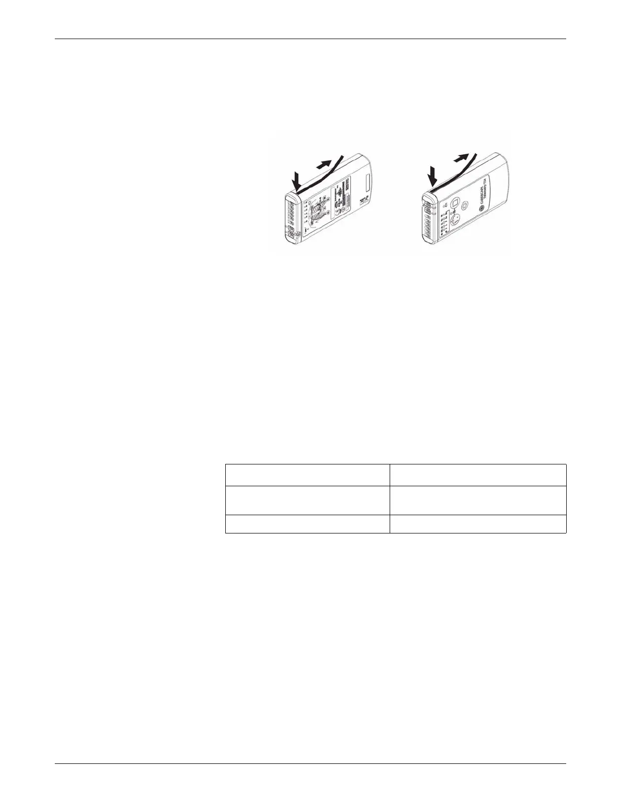
T14 side labels
The T14 transmitter also has side labels to distinguish it from an ApexPro CH
transmitter. Additional side label kits may be ordered (See T14 on page 6-23.)
321
Transmitter appearance
ApexPro transmitters have 2 user buttons: Verify Leads and Graph. They have a
white endcap on the end opposite the battery compartment cover.
The ApexPro CH and T14 transmitters have 3 user buttons: Verify Leads, Graph,
and Event Marker. There is a blue endcap on the end opposite the battery
compartment cover.
Start-up
At power-up, the transmitter LEDs flash during start-up. The following table defines
the sequence.
Refer to the ApexPro Telemetry System or CARESCAPE Telemetry T14 Operator’s
Manual for further details on transmitter operation and leadwire installation.
Transmitter interfaces
ECG Multi-Link leadwire set
The ECG connector is designed to accept 3-, 5- or 6-multi-link leadwire sets. The
ECG data is acquired from the patient through a set of leadwires. The signals are then
amplified, processed, and transmitted.
For ApexPro, ApexPro CH and T14 transmitter, the top set of pins is the ECG signal
lead. The bottom set of pins function as the signal lead shield connections. Also, the
Sequence of LED Flashes Function
All LEDs flash quickly Transmitter memory tests are being
performed.
All LEDs flash slowly twice. Indicates that all LEDs are functional.
 Loading...


