3-12 ApexPro™ 2001989-351A
Installation and configuration
260A
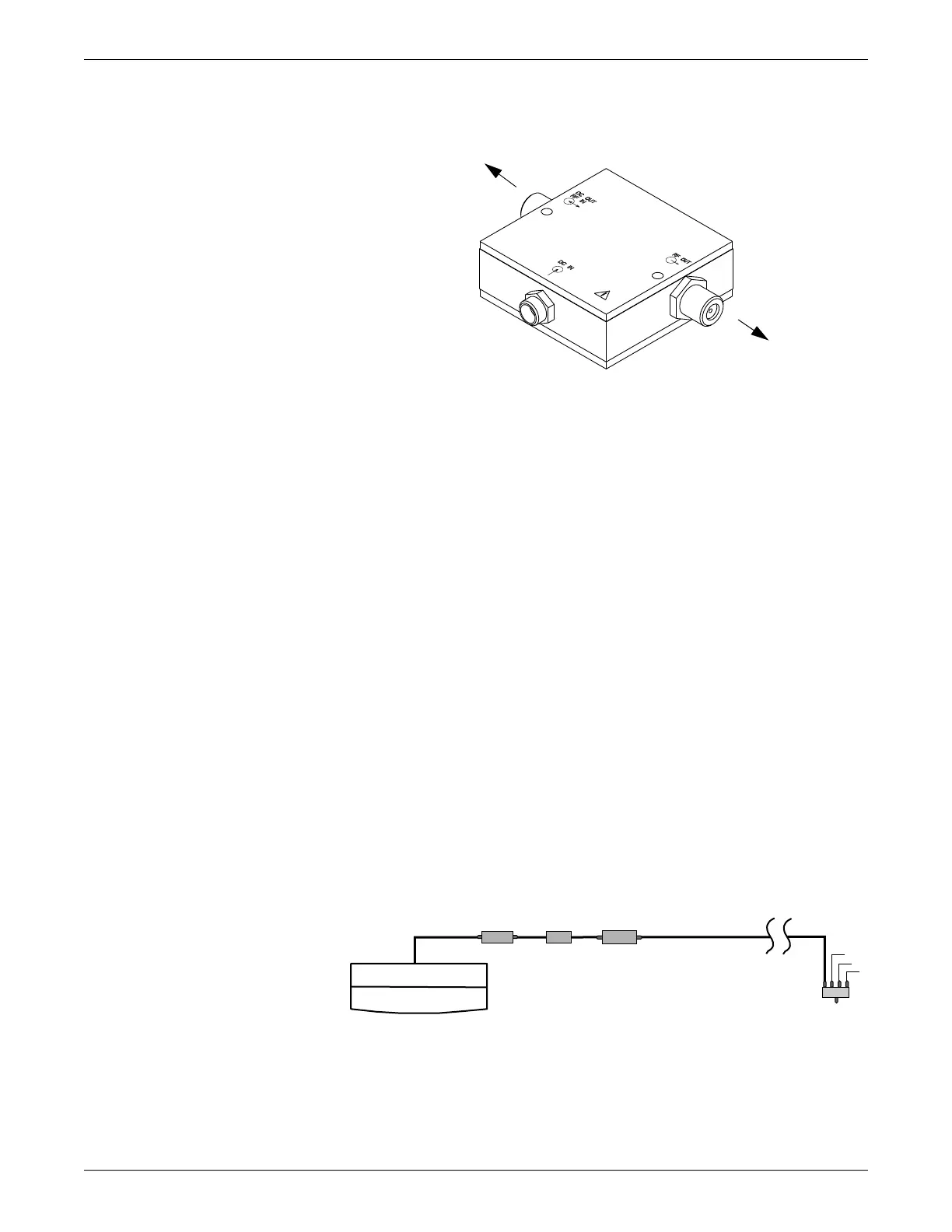
NOTE
Do not install bias tees backwards. Note the markings on the bias tee for
installation orientation. If connected backwards, the LEDs on all antennas and/or
amplifiers in that specific antenna field run will not illuminate. Neither the
antennas nor the amplifiers will work correctly.
Install notch/bandpass filters
To protect the antenna system or receiver system from signal overload, notch filters
are installed as determined by the site survey and the ND&I team. Multiple notch
filters and bandpass filters can be used on a given antenna field. Do not install notch
filters on the DC OUT/RF IN side of the bias tee because filter components may be
damaged if DC is applied. Bandpass filters are DC passing and can be installed on
either side of the bias tee.
NOTE
Use the two mounting holds to secure the Cavity Bandpass Filter 608-614 MHz
(pn 2027458-001).
With passive antennas
265A
To antenna
To receiver
system
Passive Antenna
To splitter
DC
Block
4:1
Antenna
Amplifier
Notch or
Bandpass
Filter
 Loading...


