NX-10 Installers manual
183
Testing the RSSI value
During the enrolling procedure, it is mandatory to check the RSSI value (signal strength) of the NX-
7002 and record it in the system documentation. The RSSI value is linked to the signal level of the
GSM network and ranges from 0-31, with 99 as unknown.
The RSSI value may change due to environmental circumstances, for example, additional furniture or
metal constructions. If an RSSI reading is not satisfactory, move the antenna to get a better reception.
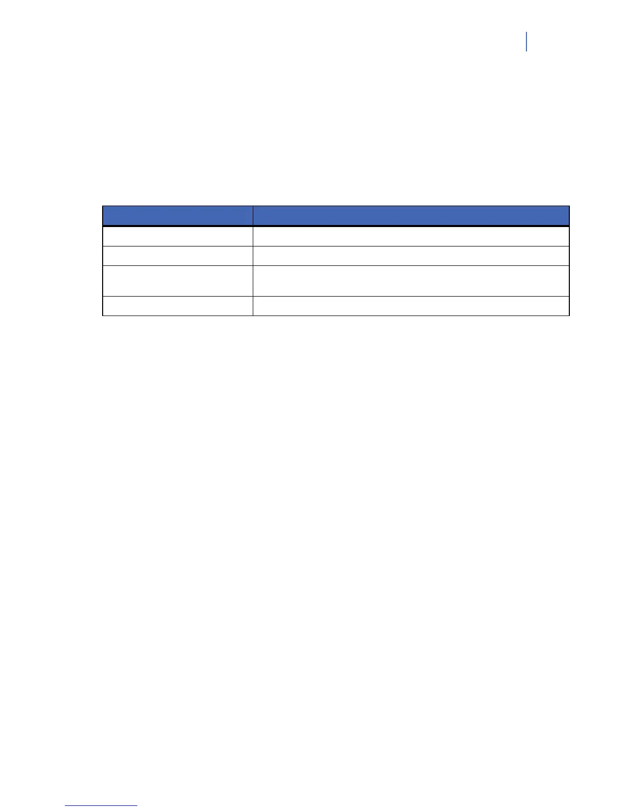
Table 20. RSSI values
Value Explanation
Values between 1 and 4 The module will not work properly and must be moved to another location.
Values between 5 and 9 The module will work but ideally should be moved to another location.
Values between 10 and 16
These are normal working values for the module located at a longer distance from
the receiver.
Values above 17 Perfect conditions.
1. Enter programming mode.
2. Select NX-7002 Module>Options>GSM>RSSI Value and press OK.
3. Note the RSSI reading.
4. Select NX-7002 Module>Options>Status Check and press OK.
5. Scroll through the status messages to ensure the SIM card is logged onto the GSM
network and the SIM card PIN is not blocked. See Obtaining the GSM/GPRS module
status on page 196 for m
ore information on status messages.
Testing the GSM or GPRS connection
• You can test if the module is logged into the GSM network by selecting NX-7002
Module>Options>Status Check>GSM Connection>Logged into GSM Network.
• You can test if the module is logged into the GPRS network by selecting NX-7002
Module>Options>GSM>Status Check>GPRS Connected.
You can also check the NETW and GPRS LEDs on the NX-10 board.
Reporting LEDs
The LEDs located on the NX-10 board indicate the current status of the GSM/GPRS module.
• The flashing BUS LED indicates that the module is receiving messages over the bus
rather than from the GSM/GPRS network.
• The NETW LED indicates that the GSM/GPRS module is currently using the GSM
network (voice channel or CSD).
• The GSM COM LED indicates that the module is connected to the GSM network.
• The SIM ERR LED indicates that the SIM card is blocked and a PUK code is
required to unblock it.
 Loading...