GR FS9040026000000000 GR FS9040025000000000
Maintenance
confidential
D.3.9
4 Service activities on the compressed-air control unit
4.1 Compressed-air control unit
3
1
2
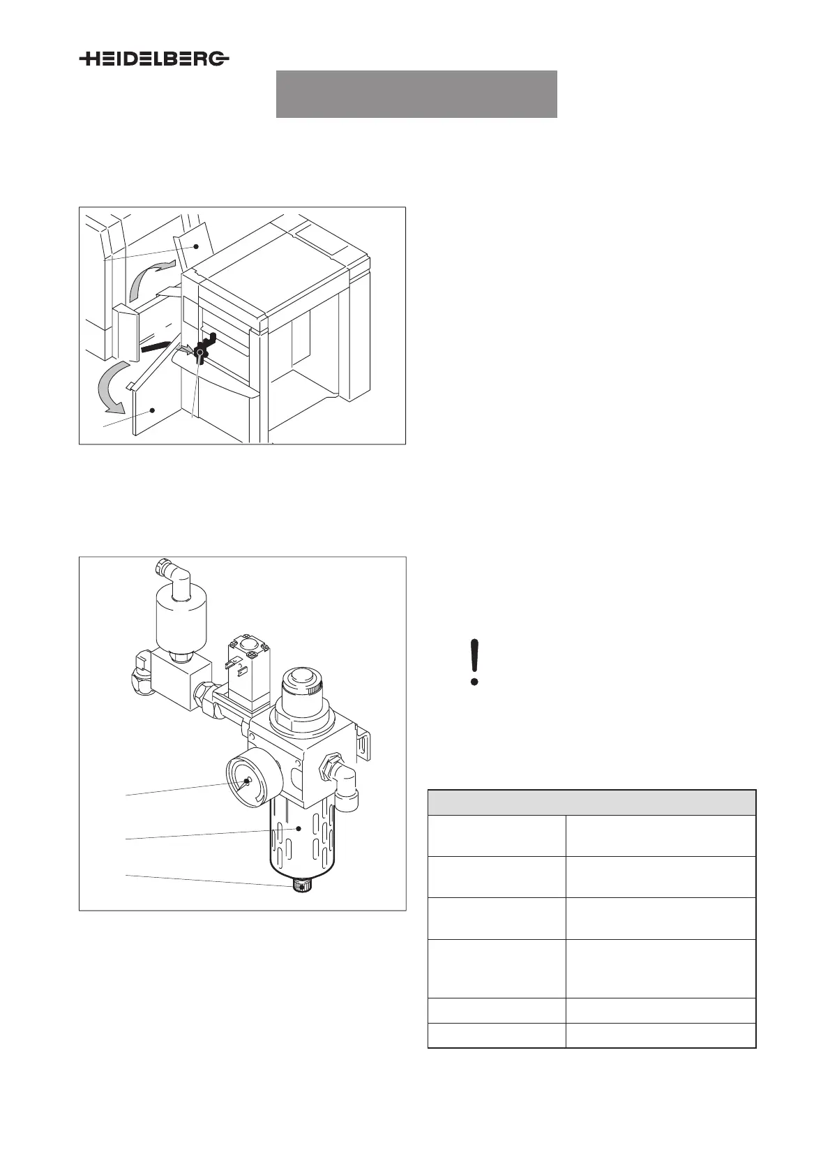
Fig. 8 Location of the compressed-air control
unit
Place of installation
1 Feeder table
2 ”Feeder” guard
3 Compressed-air control unit
The compressed-air control unit is installed on O.S.
underneath the feed table.
4.1.1 Compressed-air control unit – checking and, if necessary, the condensate
1
3
2
Fig. 9 Compressed-air control unit
1 Manometer
2 Glass cylinder
3 Drain plug
Caution –
The glass cylinder of the compressed-
air control unit (Fig. 9/1) must never be
filled completely with condensation wa-
ter. The condensation water may enter
in the pneumatic system and destroy
the pneumatic valves and pneumatic
cylinders.
Maintenance point description
Maintenance inter-
val
750 000 prints, or every
week
Maintenance loca-
tion
O.S.
Accessibility of lubri-
cating points
Open the ”feeder” guard.
Fold up the feed table.
Number/type/main-
tenance work
Check the compressed-air
control unit for condensation
water. Drain it if necessary.
Tool –
Lubricant –
Tab. 6
UTKFS9040003000000000
UTKFS9040003000000000003
 Loading...