93HEIDENHAIN TNC 426 B, TNC 430
6.2 Fundamentals of Path Functions
Programming tool movements for workpiece
machining
You create a part program by programming the path functions for
the individual contour elements in sequence. You usually do this by
entering the coordinates of the end points of the contour
elements given in the production drawing. The TNC calculates the
actual path of the tool from these coordinates, and from the tool
data and radius compensation.
The TNC moves all axes programmed in a single block
simultaneously.
Movement parallel to the machine axes
The program block contains only one coordinate. The TNC thus
moves the tool parallel to the programmed axis.
Depending on the individual machine tool, the part program is
executed by movement of either the tool or the machine table on
which the workpiece is clamped. Nevertheless, you always pro-
gram path contours as if the tool moves and the workpiece remains
stationary.
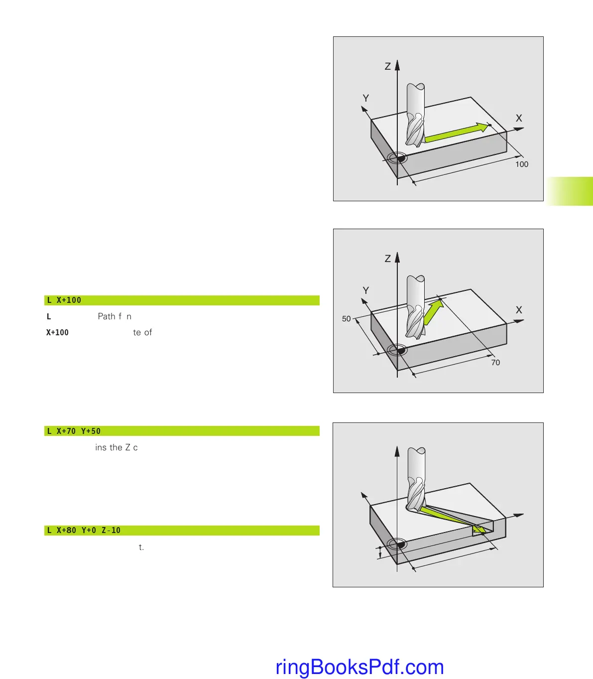
Example:
L X+100
L
Path function for “straight line”
X+100
Coordinate of the end point
The tool retains the Y and Z coordinates and moves to the position
X=100. See figure at upper right.
Movement in the main planes
The program block contains two coordinates. The TNC thus moves
the tool in the programmed plane.
Example:
L X+70 Y+50
The tool retains the Z coordinate and moves in the XY plane to the
position X=70, Y=50. See figure at center right.
Three-dimensional movement
The program block contains three coordinates. The TNC thus moves
the tool in space to the programmed position.
Example:
L X+80 Y+0 Z-10
See figure at lower right.
X
Y
Z
100
X
Y
Z
70
50
X
Y
Z
80
-10
6.2 Fundamentals of Path Functions
Gkap6.pm6 30.06.2006, 07:0493
www.EngineeringBooksPdf.com
 Loading...


