8 Programming: Cycles
228
WORKING PLANE (Cycle 19)
The functions for tilting the working plane are interfaced
to the TNC and the machine tool by the machine tool
builder. With some swivel heads and tilting tables, the
machine tool builder determines whether the entered
angles are interpreted as coordinates of the tilt axes or
as solid angles. Your machine manual provides more
detailed information.
The working plane is always tilted around the active
datum.
The fundamentals of this TNC function are described in
section 2.5 “Tilting the Working Plane.” It is important
that you read through this section thoroughly.
Effect
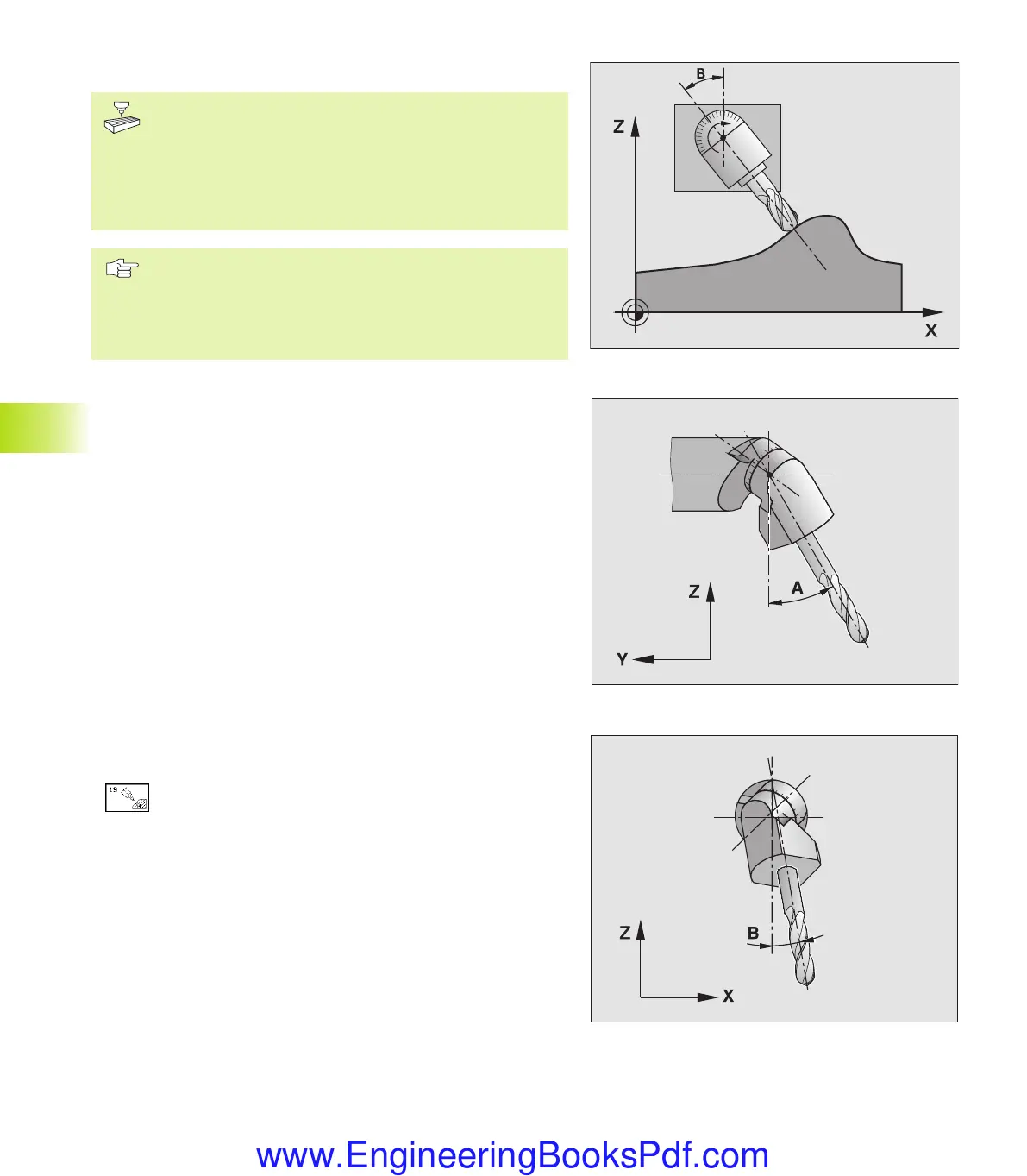
In Cycle 19 you define the position of the working plane by entering
tilt angles. The entered angles describe either the individual
positions of the tilting axes (see figure to the upper right) or the
angular components of a spatial vector (see figures at center and
lower right).
If you program the angular components of the spatial vector, the
TNC automatically calculates the angular position of the tilt axes.
The position of the spatial vector — that is the position of the tool
axis — is calculated by the TNC by rotating the machine-based
coordinate system. The axes are always rotated in the same
sequence for calculating the spatial vector: The TNC first rotates the
A axis, then the B axis, and finally the C axis.
Cycle 19 becomes effective as soon as it is defined in the program.
As soon as you move an axis in the tilted system, the
compensation for this specific axis is activated. You have to move all
axes to activate compensation for all axes.
If you set the function TILTING program run to ACTIVE in the Manual
Operation mode (see section 2.5 “Tilting the Working Plane”), the
angular value entered in this menu is overwritten by Cycle 19
WORKING PLANE.
ú
Tilt axis and tilt angle: The tilted axes of rotation
together with the associated tilt angles. The rotary
axes A, B and C are programmed using soft keys.
If the TNC automatically positions the tilted axes, you can enter the
following parameters
ú
Feed rate ? F=: Traverse speed of the rotary axis
during automatic positioning
ú
Set-up clearance ? (incremental): the TNC positions
the tilting head so that the position that results from
the extension of the tool by the set-up clearance does
not change relative to the workpiece.
8.7 Coordinate Transformation Cycles
kkap8.pm6 30.06.2006, 07:04228
www.EngineeringBooksPdf.com
 Loading...


