8 Programming: Cycles
210
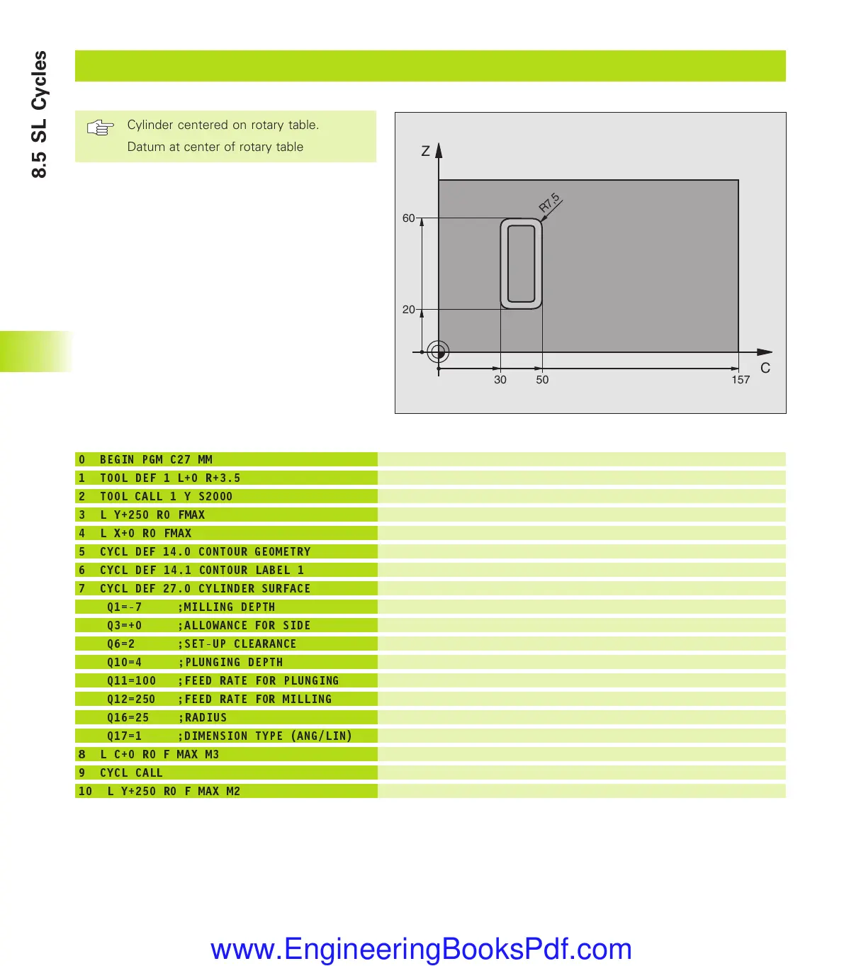
Example: Cylinder surface
Define the tool
Call tool, tool axis is Y
Retract the tool
Position tool on rotary table center
Define contour subprogram
Define machining parameters
Pre-position rotary table
Call the cycle
Retract in the tool axis, end program
0 BEGIN PGM C27 MM
1 TOOL DEF 1 L+0 R+3.5
2 TOOL CALL 1 Y S2000
3 L Y+250 R0 FMAX
4 L X+0 R0 FMAX
5 CYCL DEF 14.0 CONTOUR GEOMETRY
6 CYCL DEF 14.1 CONTOUR LABEL 1
7 CYCL DEF 27.0 CYLINDER SURFACE
Q1=-7 ;MILLING DEPTH
Q3=+0 ;ALLOWANCE FOR SIDE
Q6=2 ;SET-UP CLEARANCE
Q10=4 ;PLUNGING DEPTH
Q11=100 ;FEED RATE FOR PLUNGING
Q12=250 ;FEED RATE FOR MILLING
Q16=25 ;RADIUS
Q17=1 ;DIMENSION TYPE (ANG/LIN)
8 L C+0 R0 F MAX M3
9 CYCL CALL
10 L Y+250 R0 F MAX M2
C
Z
157
60
30
20
R7,5
50
Cylinder centered on rotary table.
Datum at center of rotary table
8.5 SL Cycles
kkap8.pm6 30.06.2006, 07:03210
www.EngineeringBooksPdf.com
 Loading...


