173HEIDENHAIN TNC 426 B, TNC 430
ú
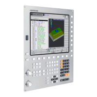
2nd set-up clearance Q204 (incremental value):
Coordinate in the tool axis at which no collision
between tool and workpiece (clamping devices) can
occur.
ú
Center in 1st axis Q216 (absolute value): Center of the
stud in the main axis of the working plane
ú
Center in 2nd axis Q217 (absolute value): Center of the
stud in the secondary axis of the working plane
ú
First side length Q218 (incremental value): Stud
length, parallel to the main axis of the working plane
ú
Second side length Q219 (incremental value): Stud
length, parallel to the secondary axis of the working
plane
ú
Corner radius Q220: Radius of the stud corner
ú
Allowance in 1st axis Q221 (incremental value):
Allowance in the main axis of the working plane
referenced to the length of the stud.
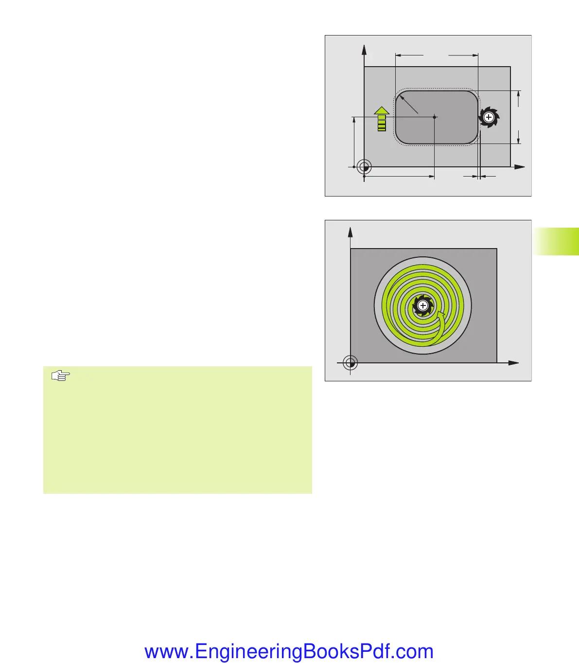
CIRCULAR POCKET MILLING (Cycle 5)
1 The tool penetrates the workpiece at the starting position (pocket
center) and advances to the first plunging depth.
2 The tool subsequently follows a spiral path at the feed rate F —
see figure at right. For calculating the stepover factor k, see Cycle
4 POCKET MILLING.
3 This process is repeated until the depth is reached.
4 At the end of the cycle, the TNC retracts the tool to the starting
position.
Before programming, note the following:
Program a positioning block for the starting point (pocket
center) in the working plane with RADIUS
COMPENSATION R0.
Program a positioning block for the starting point in the
tool axis (set-up clearance above the workpiece surface).
The algebraic sign for the depth parameter determines
the working direction.
This cycle requires a center-cut end mill (ISO 1641), or
pilot drilling at the pocket center.
X
Y
Q219
Q218
Q217
Q216
Q207
Q221
Q220
8.3 Cycle for Milling Pockets, Studs and Slots
X
Y
kkap8.pm6 30.06.2006, 07:03173
www.EngineeringBooksPdf.com
 Loading...