10 Programming: Q Parameters
276
Example: Ellipse
10.11 Programming Examples
Example: Ellipse
Center in X axis
Center in Y axis
Semiaxis in X
Semiaxis in Y
Starting angle in the plane
End angle in the plane
Number of calculating steps
Rotational position of the ellipse
Milling depth
Feed rate for plunging
Feed rate for milling
Setup clearance for pre-positioning
Define the workpiece blank
Define the tool
Call the tool
Retract the tool
Call machining operation
Retract in the tool axis, end program
0 BEGIN PGM ELLIPSE MM
1 FN 0: Q1 = +50
2 FN 0: Q2 = +50
3 FN 0: Q3 = +50
4 FN 0: Q4 = +30
5 FN 0: Q5 = +0
6 FN 0: Q6 = +360
7 FN 0: Q7 = +40
8 FN 0: Q8 = +0
9 FN 0: Q9 = +5
10 FN 0: Q10 = +100
11 FN 0: Q11 = +350
12 FN 0: Q12 = +2
13 BLK FORM 0.1 Z X+0 Y+0 Z-20
14 BLK FORM 0.2 X+100 Y+100 Z+0
15 TOOL DEF 1 L+0 R+2.5
16 TOOL CALL 1 Z S4000
17 L Z+250 R0 F MAX
18 CALL LBL 10
19 L Z+100 R0 F MAX M2
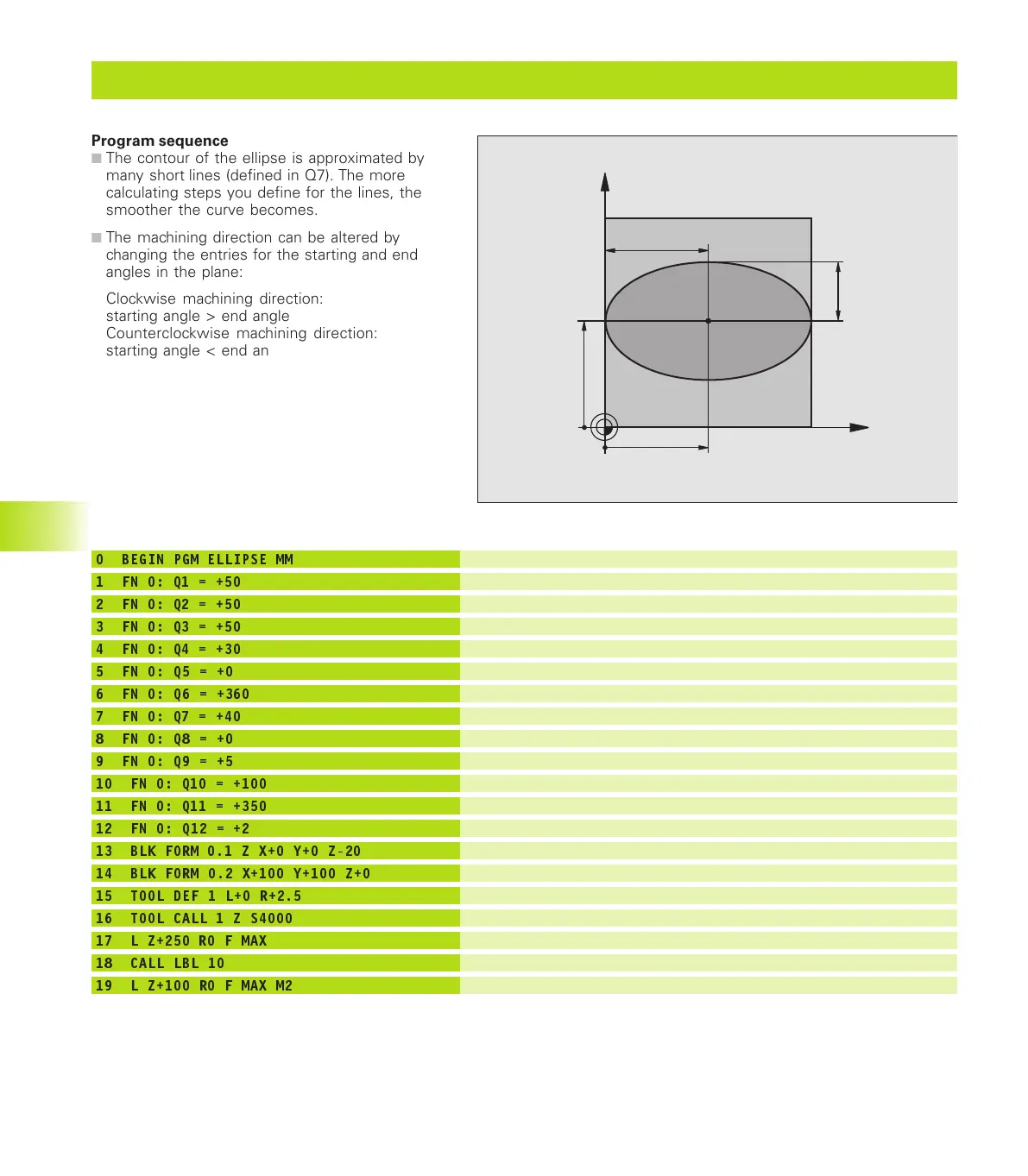
Program sequence
■
The contour of the ellipse is approximated by
many short lines (defined in Q7). The more
calculating steps you define for the lines, the
smoother the curve becomes.
■
The machining direction can be altered by
changing the entries for the starting and end
angles in the plane:
Clockwise machining direction:
starting angle > end angle
Counterclockwise machining direction:
starting angle < end angle
■
The tool radius is not taken into account.
X
Y
50
50
30
50
MKAP10.PM6 30.06.2006, 07:04276
www.EngineeringBooksPdf.com
 Loading...