HEIDENHAIN TNC 426 B, TNC 430 313
12.9 Position Display Types
In the Manual Operation mode and in the program run modes of
operation, you can select the type of coordinates to be displayed.
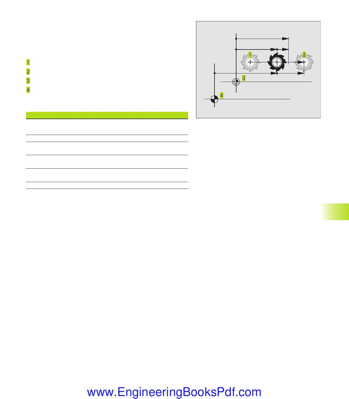
The figure at right shows the different tool positions:
Starting position
Target position of the tool
Workpiece datum
Machine datum
The TNC position displays can show the following coordinates:
Function Display
Nominal position: the value presently commanded
by the TNC NOML.
Actual position; current tool position ACTL.
Reference position: the actual position as referenced REF
to the machine datum
Distance remaining to the programmed position; DIST.
difference between actual and target position
Servo lag: difference between nominal and
actual positions LAG
Deflection of the measuring touch probe DEFL.
With the MOD function Position display 1 you can select the
position display in the status display. With Position display 2 you can
select the position display in the additional status display.
12.10 Unit of Measurement
This MOD function determines whether the coordinates are
displayed in millimeters (metric system) or inches.
■
To select the metric system (e.g. X = 15.789 mm) set the Change
mm/inches function to mm. The value is displayed with 3 digits
after the decimal point.
■
To select the inch system (e.g. X = 0.6216 inch) set the Change
mm/inches function to inches. The value is displayed to 4 decimal
places.
If you would like to activate the inch display, the TNC shows the
feed rate in inch/min. In an inch program you must enter the feed
rate large by a factor of 10.
NOML.
ACTL. LAG
REF
DIST.
12.9 Position Display Types; 12.10 Unit of Measurement
Okap12.pm6 30.06.2006, 07:04313
www.EngineeringBooksPdf.com
 Loading...