11 Test Run and Program Run
284
11.1 Graphics
11.1 Graphics
In the program run modes of operation as well as in the Test Run
mode, the TNC provides the following three display modes: Using
soft keys, select whether you desire:
■
Plan view
■ Projection in 3 planes
■
3-D view
The TNC graphic depicts the workpiece as if it were being
machined with a cylindrical end mill. If a tool table is active, you can
also simulate the machining operation with a spherical cutter. For
this purpose, enter R2 = R in the tool table.
The TNC will not show a graphic if
■
the current program has no valid blank form definition
■
no program is selected
With machine parameters 7315 to 7317 you can have the TNC
display a graphic even if no tool axis is defined or moved.
A graphic simulation is not possible for program sections
or programs in which rotary axis movements or a tilted
working plane are defined. In this case, the TNC will
display an error message.
The TNC graphic does not show a radius oversize (DR)
that has been programmed in the TOOL CALL block.
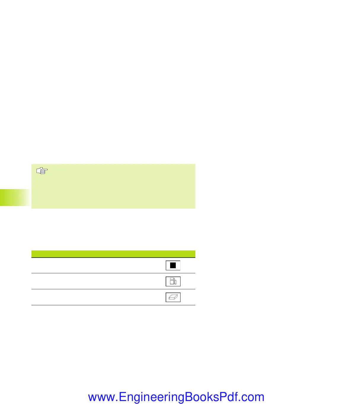
Overview of display modes
The TNC displays the following soft keys in the program run and
Test Run modes of operation:
Display mode Soft key
Plan view
Projection in 3 planes
3-D view
NKAP11.PM6 30.06.2006, 07:04284
www.EngineeringBooksPdf.com
 Loading...