<Procedures>
ATTENTION:
Turn OFF all the power source before the following procedures such as wiring, setting the rotary switch,
etc.
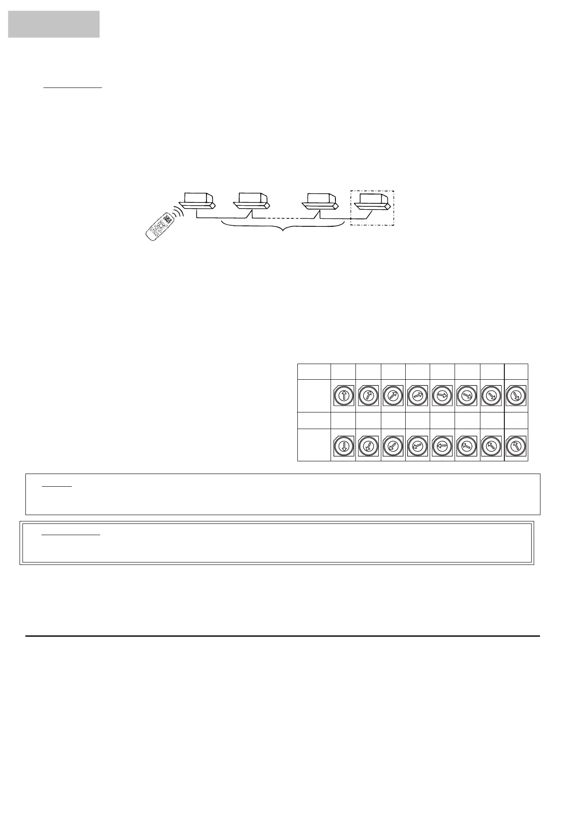
J 1) Installation of Air Panel for Wireless Control
In case of simultaneous operation of plural (up to 16) units by the wireless remote control switch, apply the air
panel for wireless control only to the unit to be operated, and apply the standard panels (for wired control) to
other units. In case of applying plural air panels for wireless control, up to 2 air panels for wireless control can
be used.
In case of applying two (2) air panels for wireless control, the setting of main and sub receiver part is required.
Refer to the receiver kit installation manual.
J 2) Perform wiring between indoor units by referring to the receiver installation manual.
J 3) Fix the connecting control cable (do not use the white cord of the 3-core cable) between indoor units at certain
points with bands not to run along the power supply cable inside of the indoor unit.
The same wiring is required outside of the indoor unit; keep a distance more than 30cm between the control
cable and the power supply cable, or ground one end of a conduit tube after inserting the control cable in the
metal conduit tube.
Wireless
Panel
Standard
Panel
Standard
Panel
Standard P
anel
or
Wireless Panel
Should be Standard Panel
Wireless
Controller
HYE-L01
J 4) Set the rotary switches (RSW) on the printed
circuit boards in the electrical box of each indoor
unit as shown in the figure below.
Rotary
Switch
Setting
Rotary
Switch
Setting
No. 0
Unit
No. 1
Unit
No. 2
Unit
No. 3
Unit
No. 4
Unit
No.5
Unit
No. 6
Unit
No. 7
Unit
No. 8
Unit
No. 9
Unit
No. 10
Unit
No. 11
Unit
No. 12
Unit
No. 13
Unit
No. 14
Unit
No. 15
Unit
0
1
2
3
4
5
6
7
8
9
A
B
C
E
F
D
0
1
2
3
4
5
6
7
8
9
A
B
C
E
F
D
0
1
2
3
4
5
6
7
8
9
A
B
C
E
F
D
0
1
2
3
4
5
6
7
8
9
A
B
C
E
F
D
0
1
2
3
4
5
6
7
8
9
A
B
C
E
F
D
0
1
2
3
4
5
6
7
8
9
A
B
C
E
F
D
0
1
2
3
4
5
6
7
8
9
A
B
C
E
F
D
0
1
2
3
4
5
6
7
8
9
A
B
C
E
F
D
0
1
2
3
4
5
6
7
8
9
A
B
C
E
F
D
0
1
2
3
4
5
6
7
8
9
A
B
C
E
F
D
0
1
2
3
4
5
6
7
8
9
A
B
C
E
F
D
0
1
2
3
4
5
6
7
8
9
A
B
C
E
F
D
0
1
2
3
4
5
6
7
8
9
A
B
C
E
F
D
0
1
2
3
4
5
6
7
8
9
A
B
C
E
F
D
0
1
2
3
4
5
6
7
8
9
A
B
C
E
F
D
0
1
2
3
4
5
6
7
8
9
A
B
C
E
F
D
NOTE:
The setting of the rotary switches (RSW) is not required for the models
which have an auto-address function.
ATTENTION:
In case that the setting of the rotary switch is not performed correctly, an abnormal operation (irregular
run/stop) may occur when test running or actual operation.
J 5) Check the Number of Indoor Units Connected
Check the number of indoor units connected when test running.
* The 7-segment indication of the receiver part shows the number of the indoor units connected in case that
the test running is performed by the controller. However, the number can not be indicated for some models.
In such a case, check the number by the wired controller .
HYXE-A01H
 Loading...