Enhanced Micro TDC 3000 User’s Manual 6-6 9/95
6.2.2
6.2.2 UCN Node Addressing (Pinning)
The NIM MODEM card (slot 10 in tower #1, for the optional redundant NIM slot 10 in
tower #2) also has a UCN node address header that must be set for the address it occupies.
If you replace this card, the node address switches must be set the same as the card that
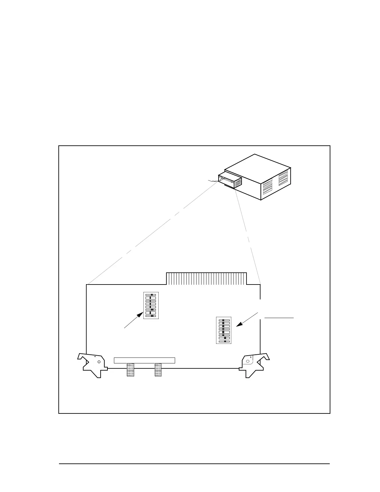
was removed. See Figure 6-3 for the location of the UCN node header.
The UCN pinning headers are set in the same way as the LCN headers, except there is a
larger address range. Acceptable UCN addresses on the Enhanced Micro TDC 3000
control system, however, are “1” for the primary NIM and “2” for the redundant NIM. To
set the UCN address, set switches to represent the weights in the node address (a switch
“OFF” is a “1”). Adjust parity so that the number of switches set to “OFF”, including the
parity switch, is an odd number.
P
64
32
16
8
4
2
1
ASSY NO. 51304511-100
ON OFF
UCN ADDRESS OFF=1
PARITY=ODD
UCN-A UCN-B
NIM MODEM
Note: The NIM MODEM circuit board is shown set for a UCN node address of five (5) with parity.
8
7
6
5
4
3
2
1
SW2
SW1
REV
CODE
OFFON
Circuit Board Revision
Switch Module
(
Do not Alter)
UCN Node Address
Switch Module
(See note)
Figure 6-3 — NIM MODEM Card 6325
 Loading...


