Galaxy Flex Installer Manual Wire detectors to zones
17
Zone configuration
Note: The circuit debounce time (the period the zone must remain in a state to register a
change in condition) is 300 ms.
The default zone configuration is 1 kΩ double-balanced with fault monitoring via a 3 kΩ
resistor (preset 11). In the following configuration a mask condition is generated if an alarm
and fault are signalled at the same time.
1. Terminate any unused zones inputs with a 1 kΩ resistor and program them as SPARE
(18).
2. If required, reprogram zone configurations and the resistance preset values using the
Zone Resistance menu (51 ent 46 ent).
3. If required, customise each zone to a specific preset using the Resistance Select menu
(52 ent 9 ent).
4. Limit the cable run on each zone to no more than 500 m. For presets 11 and 12, limit
the cable run to no more than 100 m.
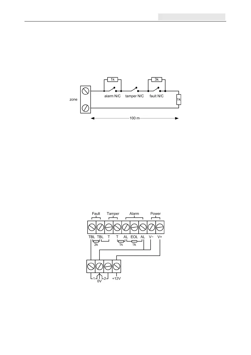
Detector connection
Wire detectors to zone terminals according to the following diagram:
Additional zone configuration information
Zones can be programmed with different resistance ranges for zone status activation (see
Zone Resistance [51.46]).
If a detector has separate fault and mask indications use the wiring shown in Figure 4.

 Loading...