Galaxy Flex Installer Manual Appendix G: Peripherals
237
Audio interface module
Using the optional audio interface module you can link two audio channels to provide audio
verification following an alarm activation. This verification in the form of recorded or live
audio captured from the area of the alarm activation is transmitted to the Alarm Receiving
Centre, along with the alarm signal. If setup, it is possible for the operator at the receiving
centre to talk back to the site. The audio channel can be assigned to more than one zone.
The Audio Interface Module is connected to the system via the RS485 line. Up to three
speaker-mic devices, such as the TP800, can be connected to each audio channel.
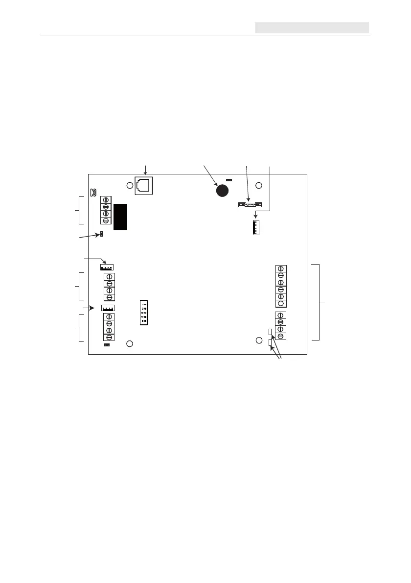
PHONE
LINE
A
B
AB
Tel ecom
Socket
Tel ecom
Connect
SKT1
Debug Header
LK4
LK3
GND
+12V
GND
SPARE
AUDIO
A
B
A
B
PA NEL
PL3
PL6
CMD 2
TMP 2
SPK 2
MIC 3
GND
+4.5V
CMD 1
TMP 1
SPK 1
MIC 1
LK2
F1
PL2
Jumper lead
RS485
termination
Engineer Header
Audio Bus
RS485
Audio
Bus
Engineer Header
RS485 line
Control Panel
RS485 line
O-wall Tamper
microswitch
Fuse for
+4.5V
Audio Channel
Ter minals (2)
Audio Expansion
Header
Diagnostic
LED's
SW3
NOTE: Audio Expansion
Header is not currently
used - it is for future
product development.
Figure 15 Audio Interface Module PCB layout
Addressing
The Audio Interface has a fixed module address.
Mounting
The module can be mounted as follows:
inside the panel in one of the peripheral mounting spaces.
inside a standard RIO box separate from the control panel.

 Loading...