Wire detectors to zones Galaxy Flex Installer Manual
18
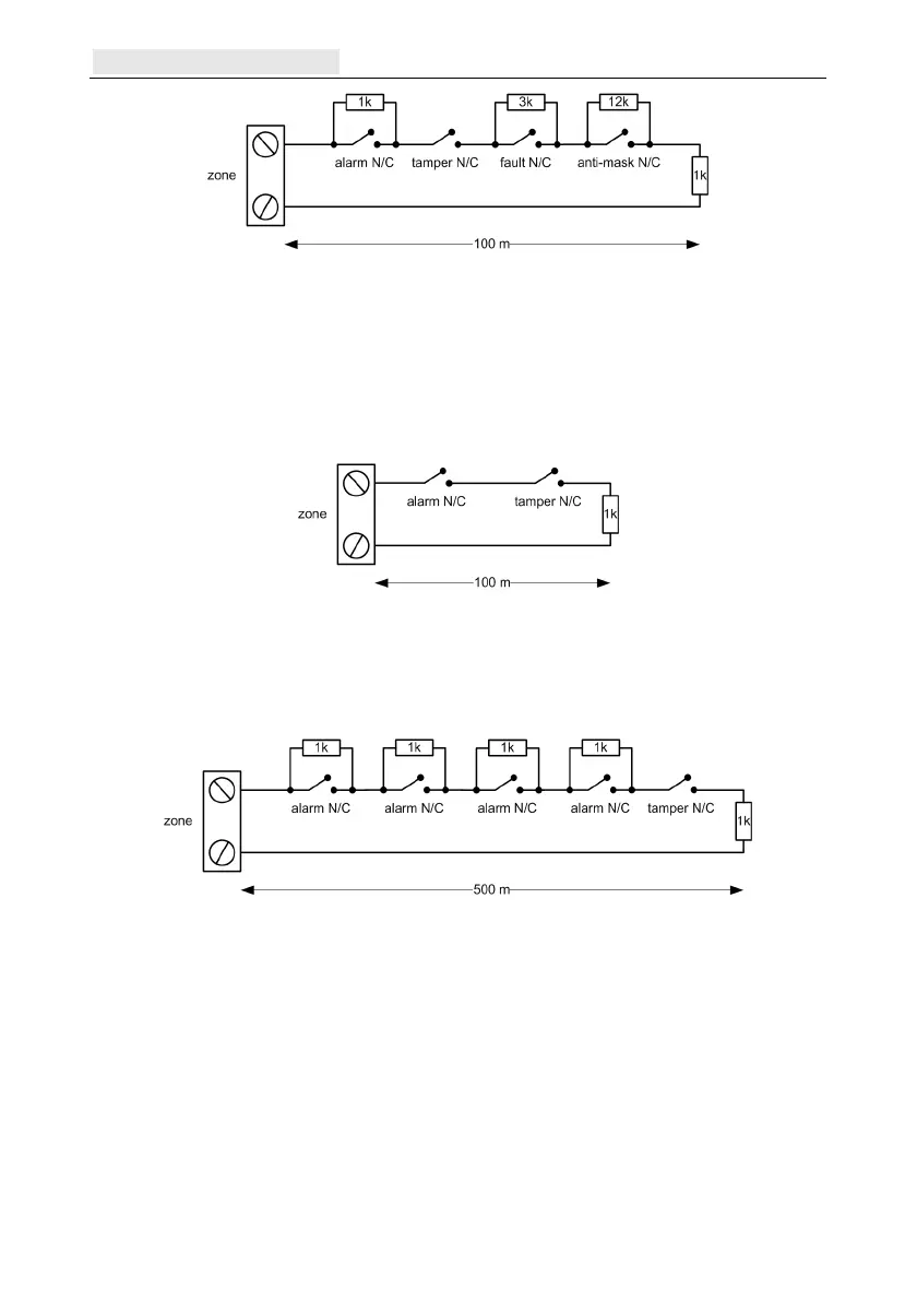
Figure 4 Option 12 - Double balanced 1k fault/mask monitoring wiring
When this wiring mode is used, ensure only one detector is set to report fault conditions, and
limit the number of detectors or contacts of any type to a maximum of 2.
Note: The recommended maximum cable run from a zone to a detector is 500 metres in all
other configurations.
In end-of-line mode use the wiring shown in Figure 5.
Figure 5 Option 10 - End of Line Zone/Detector wiring
Multiple detector wiring
Multiple detectors can be wired into a single zone when using preset 1 as shown in Figure 6.
The maximum number of detectors that can be connected to a single zone is ten.
Figure 6 Zone to multiple detector wiring
Wire keyswitches
Latching or spring loaded keyswitches can be used to set and unset the panel. To program
keyswitches, refer to Program Zones [52].
If the keyswitch latches, the transition from 1 kΩ to 2 kΩ initiates the setting procedure of
an unset system, the transition from 2 kΩ to 1 kΩ instantly unsets a set system. If the system
is already set, then the transition from 1 kΩ to 2 kΩ has no effect. If the system is unset, the
transition from 2 kΩ to 1 kΩ has no effect. This is programmed as a
Keyswitch in the
Program Zones [52] option.

 Loading...