LS10143-001SK-E Control Panel Installation
4-24
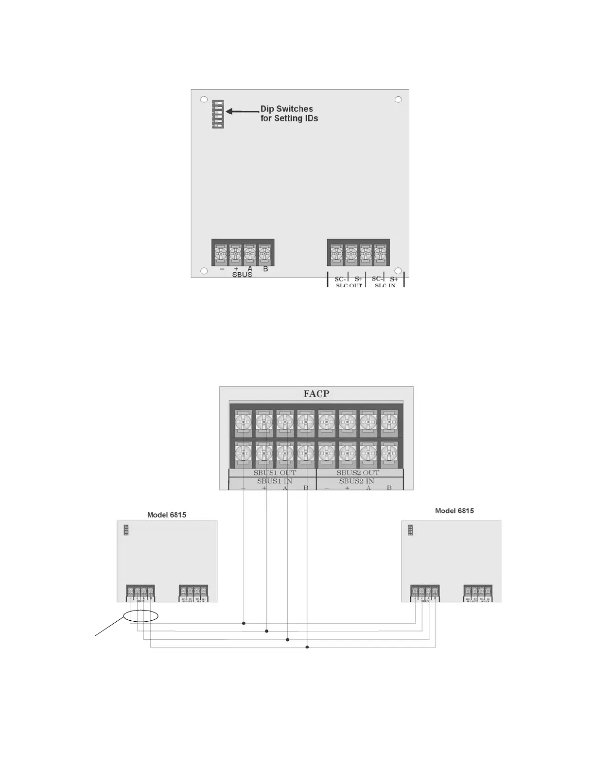
Figure 4-33 is a drawing of the 6815 board, showing the location of terminals and DIP switches.
Figure 4-33 6815 Board
4.9.1 6815 Connection to the Panel
Connect the 6815 to the control panel as shown in Figure 4-34. After the 6815 is connected to the panel, it must
be added to the system. This programming steps are described in Section 9.2.2.
Figure 4-34 6815 Connection to Main Panel Assembly
To panel via SBUS
To SLC loop

 Loading...


