LS10143-001SK-E Control Panel Installation
4-30
4.12 5865-3 / 5865-4 LED Annunciator Installation
The 5865-3 and 5865-4 are LED annunciators. The 5865-4 has 30 mappable LEDs, remote fire system silence
and fire system reset key switches, and a general system trouble LED. The 5865-3 has 30 mappable LEDs only.
These are arranged as 15 pairs of red (typically used for alarm) and yellow (typically used for trouble) LEDs.
Installation of the 5865-3 and 5865-4 is identical. The key switches and the trouble LED follow the behavior of
other system annunciators and do not require any installation steps. The following sub-sections describe how to
install the 5865-3 and 5865-4 hardware. Refer to Section 9 for programming information.
Note: This manual uses “5865” when referring to aspects of the 5865-3 and 5865-4 that are common to both
models.
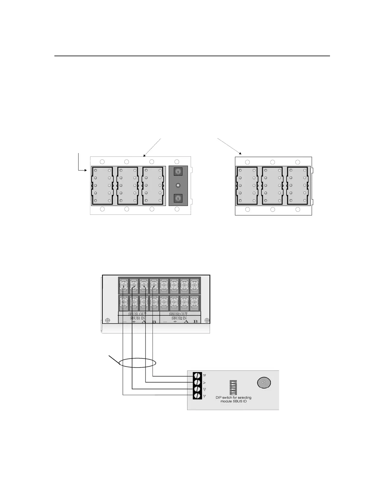
Figure 4-41 5865-3 and 5865-4 Assembly (front view)
4.12.1 FACP Connection
The 5865 connects to the panel via the SBUS. Make connections as shown in Figure 4-42. After the 5865 is
connected to the panel, it must be added to the system. This programming step is described in Section 9.2.2.
Figure 4-42 5865 Connection to the FACP
SILENCE
TROUBLE
RESET
5865-4 Board Assembly
Plexiglass plate mounted to LED board at factory.
Do not remove.
5865-4 switches
follow main FACP;
no installation
or programming
required.
Numbers indicate
point numbers for
5865. (They do
not appear on board
assembly.)
12
9
10
11 12
21 22
19 20 29 30
34
5
6
7
8
13
14
15
16
17
18
23
24
25 26
27
28

 Loading...


