LS10143-001SK-E Control Panel Installation
4-34
2. Configure the circuit through programming (see Section 9.5)
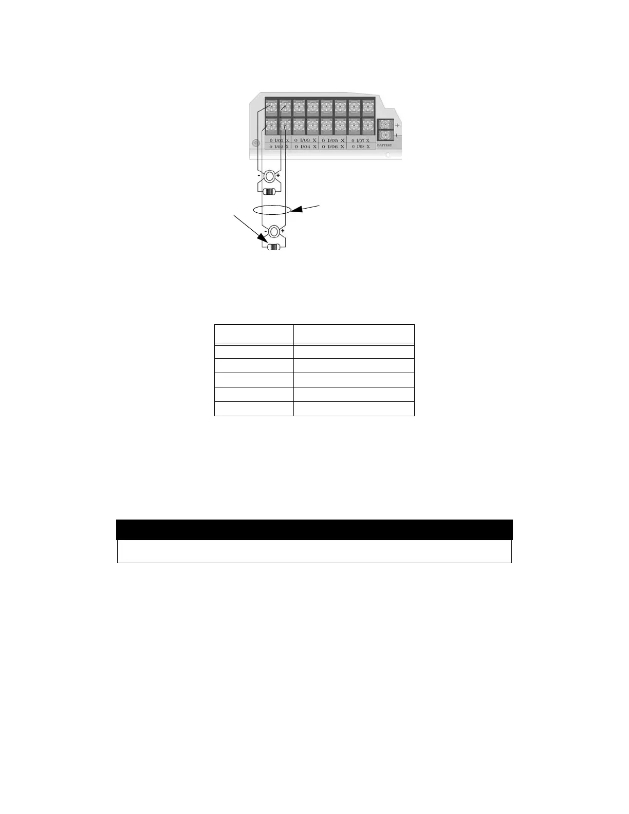
Figure 4-47 Class B Notification Appliance Circuit Wiring
Maximum voltage drop is 3V per Class B notification. See Table 4-4.
4.15.1.2 Class A Notification Wiring
You must use an appliance from the list of compatible appliances in Appendix A at the back of this manual.
To install a Class A notification appliance circuit:
1. Wire the Class A notification appliances as shown in Figure 4-48.
Table 4-4: Maximum Impedance Class B
Current Maximum Impedance
1.0A 3Ω
1.5A 2Ω
2.0A 1.5Ω
2.5A 1.2Ω
3.0A 1.0Ω
Caution!
For proper system supervision do not use looped wire under terminals marked O and X of the Flexput
connectors. Break wire runs to provide supervision of connections.
power limited supervised
notification wiring
regulated 24 VDC
3A per circuit, 9A max combined
4.7 kΩ
EOL
alarm polarity shown

 Loading...


